This story originally appeared at InnerFidelity.com
I spend a lot of time measuring headphones and talking about the measurements. Well ... why hog all the fun? Below you'll find a step by step run-through of InnerFidelity's headphone measurement procedure for InnerFidelity's headphone measurements, which can be found here.
Enjoy!
Headphone Measurement Proceedures - Introduction and Equipment
Headphone Objective Measurements Overview
There are two camps in the world of audio: objectivists and subjectivists. In an oversimplified summary, objectivists believe audio performance is measurable; subjectivists believe audio performance can only be evaluated as an experience. There are, of course, those with a more sophisticated and balanced perspective who believe both have merit; I fall into that camp. I can look at a set of measurements and can tell you roughly what to expect when you put the cans on, but there's no way to really tell what the experience is going to be like until you listen. None the less, having a good database of measurements will let you know if one headphone has more bass than another; will allow you to rapidly find headphones of similar characteristics; and will let you rule out poorly performing headphones without having to listen. Unlike speakers, which are more complicated with multiple drivers and crossovers, and get put in rooms with reflections from walls, headphones are usually a single driver directly coupled to your ears. As a result, my experience leads me to believe the relationship is closer between headphone measurements and what you hear, than speaker measurements and what you hear. Similarly, audio electronics gear these days is quite good, and measures of their performance is rather more like splitting hairs --- the difference between 0.001% and 0.0001% distortion is not easily audible. The imperfections of headphones are orders of magnitude larger than electronics gear, so, while I believe it is important to measure electronic gear, I also feel it tends to be less informative regarding the experienced sound quality than headphone measurements.
What I'm trying to get at here is that I've found the correlation between headphone measurements and the listening experience quite a bit stronger than with speaker or electronics measurements. Though this may simply be a result of my intimate familiarity with headphone measurements. At any rate, I think you'll find this journey into objective headphone evaluation interesting and illuminating.
Headphone Measurement Equipment Overview
The Head Acoustics HMS II.3 Head Simulator
The heart of a headphone measurement system is a microphone in the shape of a head. I use a Head Acoustics HMSII.3 head acoustics simulator. At around $20,000, this noggin ain't cheap, but it's got a lot of very specialized characteristics and careful engineering that make it a very important tool.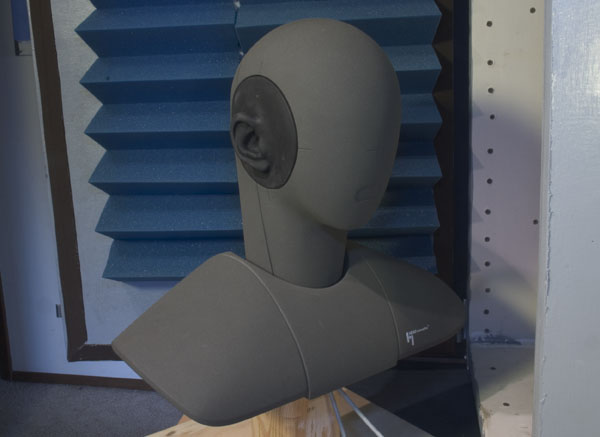 The Head Acoustics HMSII.3 head acoustics simulator.
The head is designed to act exactly like the average human listening system. Inside the head at very much the same position of your eardrums at the end of your ear canal, are two very special microphones (one in each ear) that mimic the exact acoustic impedance characteristics of your eardrum. The shape of the ears is also very precisely defined (IEC specification 60268-7) so as to act just like the average human ear. The goal of this device is to provide a measurement of exactly what is heard at the eardrum for sound arriving at the head. Because headphones are coupled directly to the head, it is only by using a device such as this that headphone measurements can be made that relate strongly to what we hear. There are other headphone measurement couplers, which are not head shaped, that can achieve similar results, but the head allows me to measure both ears at the same time, and allows me to measure the amount of isolation from outside noise accurately.
The Test Chamber
In order to achieve repeatable measurements, I need to have a way to isolate the head from random outside noise that might appear in the measurements. Also, because one of the measurements needed is the amount of isolation from outside noise, I need an environment in which I can repeatably create a controlled amount of noise. To do this I've built a custom chamber in which to place the head during tests. It's about 4'x2'x2' and is constructed of 1” furniture grade plywood with a layer of drywall very thoroughly glued to the inside walls. The very heavy and stiff walls provide significant acoustic resistance; I currently get about 15dB of isolation from outside noise. This chamber is mounted on air bladders (wheel barrow innertubes) in order to isolate it from mechanically born noise from the rest of my home. Cables are routed through a hole in the chamber that is filled in with modeling clay.
The Head Acoustics HMSII.3 head acoustics simulator.
The head is designed to act exactly like the average human listening system. Inside the head at very much the same position of your eardrums at the end of your ear canal, are two very special microphones (one in each ear) that mimic the exact acoustic impedance characteristics of your eardrum. The shape of the ears is also very precisely defined (IEC specification 60268-7) so as to act just like the average human ear. The goal of this device is to provide a measurement of exactly what is heard at the eardrum for sound arriving at the head. Because headphones are coupled directly to the head, it is only by using a device such as this that headphone measurements can be made that relate strongly to what we hear. There are other headphone measurement couplers, which are not head shaped, that can achieve similar results, but the head allows me to measure both ears at the same time, and allows me to measure the amount of isolation from outside noise accurately.
The Test Chamber
In order to achieve repeatable measurements, I need to have a way to isolate the head from random outside noise that might appear in the measurements. Also, because one of the measurements needed is the amount of isolation from outside noise, I need an environment in which I can repeatably create a controlled amount of noise. To do this I've built a custom chamber in which to place the head during tests. It's about 4'x2'x2' and is constructed of 1” furniture grade plywood with a layer of drywall very thoroughly glued to the inside walls. The very heavy and stiff walls provide significant acoustic resistance; I currently get about 15dB of isolation from outside noise. This chamber is mounted on air bladders (wheel barrow innertubes) in order to isolate it from mechanically born noise from the rest of my home. Cables are routed through a hole in the chamber that is filled in with modeling clay.
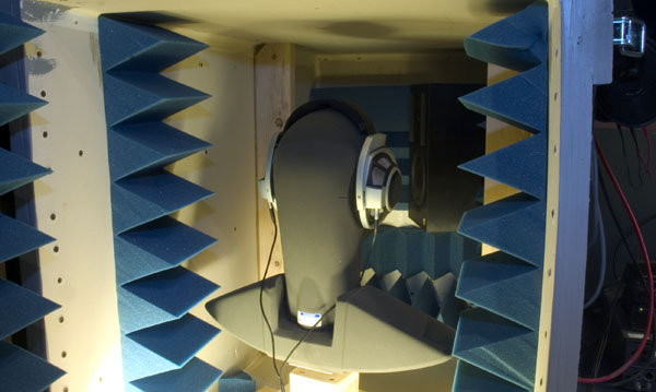 My home-brewed acoustic isolation chamber for testing headphones.
The chamber has a speaker in it that is used to generate pink noise for measuring isolation. The interior of the chamber has some noise damping foam, but also has reflective surfaces designed to evenly distribute noise around the chamber interior so that the sound approaches the headphones from many directions when measuring isolation.
The Audio Precision System 2 Cascade
My home-brewed acoustic isolation chamber for testing headphones.
The chamber has a speaker in it that is used to generate pink noise for measuring isolation. The interior of the chamber has some noise damping foam, but also has reflective surfaces designed to evenly distribute noise around the chamber interior so that the sound approaches the headphones from many directions when measuring isolation.
The Audio Precision System 2 Cascade
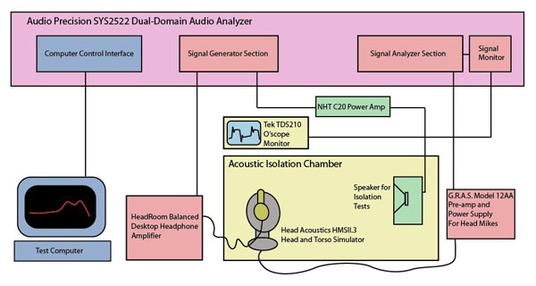
 The Audio Precision System Two Cascade, model SYS2522 dual-domain audio tester.
Once we have a way to accurately simulate the acoustics of headphone listening, we need a piece of gear that is able to generate and analyze the audio signals needed to tease out meaningful measurements. I use an Audio Precision System 2 Cascade dual-domain audio tester. This piece of gear can generate and analyze both analog and digital audio signals with state-of-the-art precision and can be programmed to automatically run the device under test through a broad battery of standard and customized tests. I think if the AP had a soul, I'd marry it. Unfortunately it doesn't, so I settle for a healthy dose of gear lust whenever I get to play with it.
The Computer
The Audio Precision System Two Cascade, model SYS2522 dual-domain audio tester.
Once we have a way to accurately simulate the acoustics of headphone listening, we need a piece of gear that is able to generate and analyze the audio signals needed to tease out meaningful measurements. I use an Audio Precision System 2 Cascade dual-domain audio tester. This piece of gear can generate and analyze both analog and digital audio signals with state-of-the-art precision and can be programmed to automatically run the device under test through a broad battery of standard and customized tests. I think if the AP had a soul, I'd marry it. Unfortunately it doesn't, so I settle for a healthy dose of gear lust whenever I get to play with it.
The Computer
A fairly old PC controls the Audio Precision (AP); nothing special here. The PC is loaded with a software application that controls the AP, and receives measured data, which it inserts into preconfigured Excel spreadsheet templates. The AP software has control panels, which can be configured into the various tests (frequency response, %THD+noise, impulse response, etc), and then called by a script written in an AP extended basic programming language. It is possible to “drive” the AP manually from these pre-configure panel set-ups to do custom experiments. Other Gear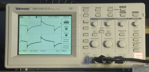 The Tektronics model TDS 210 digital oscilloscope used to monitor signals while positioning headphones.
A small Tektronix TDS 210 oscilloscope is mounted above the door of the chamber and is fed left and right channel signals from the monitor output of the AP. I use this o'scope to monitor the signal from the head in order to properly position the headphones on the head prior to test. Positioning of the headphones is critical, and the o'scope provides important feedback on whether or not the headphones are positioned and sealing properly.
The microphones in the head have phantom power voltage and pre-amplification provided by a G.R.A.S. Type 12AA low-noise pre-amplifier mounted next to the chamber. The speaker in the chamber is driven by an NHT C20 power amplifier.
The Tektronics model TDS 210 digital oscilloscope used to monitor signals while positioning headphones.
A small Tektronix TDS 210 oscilloscope is mounted above the door of the chamber and is fed left and right channel signals from the monitor output of the AP. I use this o'scope to monitor the signal from the head in order to properly position the headphones on the head prior to test. Positioning of the headphones is critical, and the o'scope provides important feedback on whether or not the headphones are positioned and sealing properly.
The microphones in the head have phantom power voltage and pre-amplification provided by a G.R.A.S. Type 12AA low-noise pre-amplifier mounted next to the chamber. The speaker in the chamber is driven by an NHT C20 power amplifier.
 Measuring Frequency Response
I could write a book about what a headphone frequency response measurement means --- and over a bit of time I will right here :) --- but for the moment we're going to talk mostly about how the measurement is made, with just a few basics thrown in to help us follow along. Headphone acoustics are significantly different than room acoustics because you are using an acoustic coupler as opposed to propagating the sound through free-space --- technically called the “free field” in audio terminology, and defined as three-dimensional space where there are no reflecting surfaces. When measuring speakers, you measure the sound out in the free field with a reference microphone and assume if the sound measures flat, you'll hear it as flat if you put your head where the microphone was --- which is true. But with headphones, there is no free field in which to measure the sound. Due to reflections and modal oscillations within the enclosed volume between the headphones and your ear, the sound at any particular point within that space may be different than the sound at another point. As a result, the only legitimate place to measure the sound from headphones is at the eardrum. That's a problem because if the sound is flat out in the free field and you stick your head in it, the sound is no longer flat by the time it hits your eardrum. This difference between flat sound in the free field, and the EQ of the sound you hear at the eardrum when you stick your head in the sound in the free field, is called the Head Related Transfer Function.
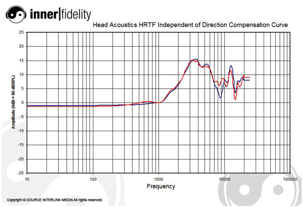 Figure 1 shows the independent of direction Head Related Transfer Function of the Head Acoustics HMSII.3 head acoustics simulator.
Multiple things come into play that effect the EQ of the sound reaching your eardrum:
The other problem is that the earphone coupler has internal dimensions that allow modal artifacts to appear. These are like the room modes you try to damp with acoustic treatments in your listening room, but occur at much higher frequencies due to the small size of the chamber. These artifacts will move around as the size and shape of the enclosed volume changes with the position of the headphones on the ear. Therefore it is important to carefully measure the headphones in a number of different positions to get a true idea of the acoustic energy being emitted from the drivers. This is called spatial averaging.
Headphones must be measured in multiple positions to more accurately reflect the acoustic energy in the system.
Now that we know these two facts (that there is a HRTF we have to compensate for, and the headphones need to be measured in multiple positions) we can get down to the process of how a headphones frequency response can be measured.
Positioning the Headphones
Figure 1 shows the independent of direction Head Related Transfer Function of the Head Acoustics HMSII.3 head acoustics simulator.
Multiple things come into play that effect the EQ of the sound reaching your eardrum:
The other problem is that the earphone coupler has internal dimensions that allow modal artifacts to appear. These are like the room modes you try to damp with acoustic treatments in your listening room, but occur at much higher frequencies due to the small size of the chamber. These artifacts will move around as the size and shape of the enclosed volume changes with the position of the headphones on the ear. Therefore it is important to carefully measure the headphones in a number of different positions to get a true idea of the acoustic energy being emitted from the drivers. This is called spatial averaging.
Headphones must be measured in multiple positions to more accurately reflect the acoustic energy in the system.
Now that we know these two facts (that there is a HRTF we have to compensate for, and the headphones need to be measured in multiple positions) we can get down to the process of how a headphones frequency response can be measured.
Positioning the Headphones
Rough positioning of the headphones is done by eye; the ears on the head have indexing marks around the edge of the rubber insert that allow me to visually see if the headphone is roughly centered on the ear. Then using a 30Hz square wave playing through the headphones, I monitor the signal from the head on the oscilloscope to more finely position the cans on the dummy head.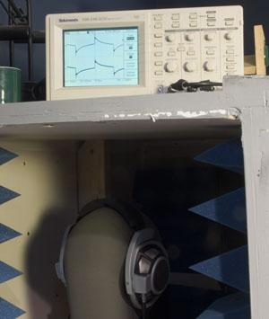 By observing the signal carefully, I can tell whether the headphones are sealing properly, and I can tell how the quality of the signal changes with position. Once satisfied that the headphones are optimally positioned, I move them slightly forward for the first of five measurements. The amount I move them forward (and later back, up down, and centered) is small, and somewhat dependent on the headphone. Some headphones have large earpieces and I might move the headphones five millimeters in each direction away from center. Some on-ear headphones are so sensitive to movement due to the difficulty of achieving a seal that I can move them only a millimeter or two before the seal breaks. Basically, I try to move the headphones within the range that average competent user would experience in the real world, and within a range that the headphone appears to be delivering good performance.
Gathering the Data
By observing the signal carefully, I can tell whether the headphones are sealing properly, and I can tell how the quality of the signal changes with position. Once satisfied that the headphones are optimally positioned, I move them slightly forward for the first of five measurements. The amount I move them forward (and later back, up down, and centered) is small, and somewhat dependent on the headphone. Some headphones have large earpieces and I might move the headphones five millimeters in each direction away from center. Some on-ear headphones are so sensitive to movement due to the difficulty of achieving a seal that I can move them only a millimeter or two before the seal breaks. Basically, I try to move the headphones within the range that average competent user would experience in the real world, and within a range that the headphone appears to be delivering good performance.
Gathering the Data
Once the headphone is in position, I close the chamber and push the button to start the frequency response sweep. A 500Hz test tone is played, and the system regulates the tone to be 90dB SPL the eardrum of the head. This sets the amplitude of the signal generator for the test. I use 90dB SPL because I take it to be a loud listening level that headphones should be able to comfortably achieve. The IEC spec calls out 94dB, but I feel this level puts undue stress on headphones and would result in measurements that do not reflect the sound heard by most users. Because the purpose of the database I'm building is to give users characteristic information about the sound of headphones during normal listening I think this is a legitimate level. During the Total Harmonic Distortion tests, however, I measure both at the 90dB level and the 100dB level. If one were to listen to music at 90dB average, peaks in the materials could easily achieve 100dB. Therefore, I think it is important to see what distortions are encountered at a level somewhat higher than the IEC specified 94dB.
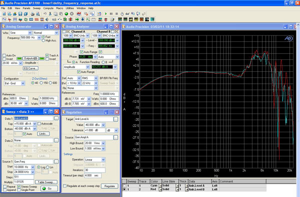 Screenshot of the Audio Precision panel set-up during frequency response measurements.
Once the reference level is set, the generator is set to sweep from 10Hz to 22kHz in 511 logarithmically equal steps. The AP analyzer measures the amplitude at each step and plots it as the raw frequency response for that headphone position. It then beeps letting me know that I need to move the headphones to the next position. I repeat the process positioning the headphones a total of five times (forward, back, up, down, centered), and the system spits all the data out into a spreadsheet.
Once in the spreadsheet, the data for all five measurements for each channel (left and right) are added together and divided by five. This provides the spatial averaging needed to reduce modal artifacts, and get a truer idea of the amount of acoustic energy available to be coupled into the ear.
Once a spatially averaged data set is created for the raw frequency response, the HRTF curve is subtracted. This is the step that compensates for the differences in EQ between the sound in the free field and the sound heard at the eardrum. The exact nature of this EQ curve is quite complicated, as I mentioned above, and there are three HRTF curves that come with the head as it's calibration curves.
Free Field – The HRTF when a sound is emitted from a source directly in front of the head in an anechoic environment.
Diffuse Field – The HRTF when sound is coming at the head from all directions simultaneously.
Independent of Direction – A rather recently developed HRTF to measure real world sounds in less abstract and highly conditional situations than the two cases above.
I would prefer to have an HRTF calibration curve for the special conditions of two speakers placed 30 degree off axis as that is what the headphones are trying to simulate, but no such calibration exists. After lengthy discussion with the applications engineers at Head Acoustics, the Independent of Direction HRTF was picked as the most applicable for my purposes. In the end, it doesn't matter too much as none of them are perfect, and since all headphones have the same HRTF applied, measurements are legitimate for comparative purposes. It is important to remember though, that even if there were such a thing as the perfect headphone, its frequency response as measured would not be flat due to these complexities.
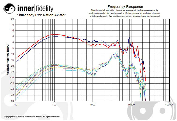
A finished set of frequency response curves.
In the final product frequency response graphs here at InnerFidelity, you see the ten raw frequency response measurements (five left and five right)at the bottom of the chart. The spatially averaged and HRTF compensated frequency response for the headphones is at the top of the chart.
How close is this to the truth? Well ... it was the truth on that day, with that head, with those ears, in those positions. Will it sound like that to you? No ... but pretty close ... as close as it gets when it comes to objective measurements anyway --- this is pretty good gear. Here's the important thing: a lot of variables are accounted for, and the measurements I take today and next year will be useful and valid comparisons. The database will get pretty big over time. In producing a database of headphone measurements, InnerFidelity will bring you a whole big chunk of truth. That tickles me pink.
Will it be everything you need to know? No, it may help guide you quite a bit, but you'll still have to wrap the cans around your head to know what they sound like to you.
Ain't that nice.
Happy listening!
Screenshot of the Audio Precision panel set-up during frequency response measurements.
Once the reference level is set, the generator is set to sweep from 10Hz to 22kHz in 511 logarithmically equal steps. The AP analyzer measures the amplitude at each step and plots it as the raw frequency response for that headphone position. It then beeps letting me know that I need to move the headphones to the next position. I repeat the process positioning the headphones a total of five times (forward, back, up, down, centered), and the system spits all the data out into a spreadsheet.
Once in the spreadsheet, the data for all five measurements for each channel (left and right) are added together and divided by five. This provides the spatial averaging needed to reduce modal artifacts, and get a truer idea of the amount of acoustic energy available to be coupled into the ear.
Once a spatially averaged data set is created for the raw frequency response, the HRTF curve is subtracted. This is the step that compensates for the differences in EQ between the sound in the free field and the sound heard at the eardrum. The exact nature of this EQ curve is quite complicated, as I mentioned above, and there are three HRTF curves that come with the head as it's calibration curves.
Free Field – The HRTF when a sound is emitted from a source directly in front of the head in an anechoic environment.
Diffuse Field – The HRTF when sound is coming at the head from all directions simultaneously.
Independent of Direction – A rather recently developed HRTF to measure real world sounds in less abstract and highly conditional situations than the two cases above.
I would prefer to have an HRTF calibration curve for the special conditions of two speakers placed 30 degree off axis as that is what the headphones are trying to simulate, but no such calibration exists. After lengthy discussion with the applications engineers at Head Acoustics, the Independent of Direction HRTF was picked as the most applicable for my purposes. In the end, it doesn't matter too much as none of them are perfect, and since all headphones have the same HRTF applied, measurements are legitimate for comparative purposes. It is important to remember though, that even if there were such a thing as the perfect headphone, its frequency response as measured would not be flat due to these complexities.
A finished set of frequency response curves.
In the final product frequency response graphs here at InnerFidelity, you see the ten raw frequency response measurements (five left and five right)at the bottom of the chart. The spatially averaged and HRTF compensated frequency response for the headphones is at the top of the chart.
How close is this to the truth? Well ... it was the truth on that day, with that head, with those ears, in those positions. Will it sound like that to you? No ... but pretty close ... as close as it gets when it comes to objective measurements anyway --- this is pretty good gear. Here's the important thing: a lot of variables are accounted for, and the measurements I take today and next year will be useful and valid comparisons. The database will get pretty big over time. In producing a database of headphone measurements, InnerFidelity will bring you a whole big chunk of truth. That tickles me pink.
Will it be everything you need to know? No, it may help guide you quite a bit, but you'll still have to wrap the cans around your head to know what they sound like to you.
Ain't that nice.
Happy listening!
There are two camps in the world of audio: objectivists and subjectivists. In an oversimplified summary, objectivists believe audio performance is measurable; subjectivists believe audio performance can only be evaluated as an experience. There are, of course, those with a more sophisticated and balanced perspective who believe both have merit; I fall into that camp. I can look at a set of measurements and can tell you roughly what to expect when you put the cans on, but there's no way to really tell what the experience is going to be like until you listen. None the less, having a good database of measurements will let you know if one headphone has more bass than another; will allow you to rapidly find headphones of similar characteristics; and will let you rule out poorly performing headphones without having to listen. Unlike speakers, which are more complicated with multiple drivers and crossovers, and get put in rooms with reflections from walls, headphones are usually a single driver directly coupled to your ears. As a result, my experience leads me to believe the relationship is closer between headphone measurements and what you hear, than speaker measurements and what you hear. Similarly, audio electronics gear these days is quite good, and measures of their performance is rather more like splitting hairs --- the difference between 0.001% and 0.0001% distortion is not easily audible. The imperfections of headphones are orders of magnitude larger than electronics gear, so, while I believe it is important to measure electronic gear, I also feel it tends to be less informative regarding the experienced sound quality than headphone measurements.
The heart of a headphone measurement system is a microphone in the shape of a head. I use a Head Acoustics HMSII.3 head acoustics simulator. At around $20,000, this noggin ain't cheap, but it's got a lot of very specialized characteristics and careful engineering that make it a very important tool.
The Head Acoustics HMSII.3 head acoustics simulator.
The head is designed to act exactly like the average human listening system. Inside the head at very much the same position of your eardrums at the end of your ear canal, are two very special microphones (one in each ear) that mimic the exact acoustic impedance characteristics of your eardrum. The shape of the ears is also very precisely defined (IEC specification 60268-7) so as to act just like the average human ear. The goal of this device is to provide a measurement of exactly what is heard at the eardrum for sound arriving at the head. Because headphones are coupled directly to the head, it is only by using a device such as this that headphone measurements can be made that relate strongly to what we hear. There are other headphone measurement couplers, which are not head shaped, that can achieve similar results, but the head allows me to measure both ears at the same time, and allows me to measure the amount of isolation from outside noise accurately.
My home-brewed acoustic isolation chamber for testing headphones.
The chamber has a speaker in it that is used to generate pink noise for measuring isolation. The interior of the chamber has some noise damping foam, but also has reflective surfaces designed to evenly distribute noise around the chamber interior so that the sound approaches the headphones from many directions when measuring isolation.
The Audio Precision System 2 Cascade
The Audio Precision System Two Cascade, model SYS2522 dual-domain audio tester.
Once we have a way to accurately simulate the acoustics of headphone listening, we need a piece of gear that is able to generate and analyze the audio signals needed to tease out meaningful measurements. I use an Audio Precision System 2 Cascade dual-domain audio tester. This piece of gear can generate and analyze both analog and digital audio signals with state-of-the-art precision and can be programmed to automatically run the device under test through a broad battery of standard and customized tests. I think if the AP had a soul, I'd marry it. Unfortunately it doesn't, so I settle for a healthy dose of gear lust whenever I get to play with it.
A fairly old PC controls the Audio Precision (AP); nothing special here. The PC is loaded with a software application that controls the AP, and receives measured data, which it inserts into preconfigured Excel spreadsheet templates. The AP software has control panels, which can be configured into the various tests (frequency response, %THD+noise, impulse response, etc), and then called by a script written in an AP extended basic programming language. It is possible to “drive” the AP manually from these pre-configure panel set-ups to do custom experiments. Other Gear
The Tektronics model TDS 210 digital oscilloscope used to monitor signals while positioning headphones.
A small Tektronix TDS 210 oscilloscope is mounted above the door of the chamber and is fed left and right channel signals from the monitor output of the AP. I use this o'scope to monitor the signal from the head in order to properly position the headphones on the head prior to test. Positioning of the headphones is critical, and the o'scope provides important feedback on whether or not the headphones are positioned and sealing properly.
The microphones in the head have phantom power voltage and pre-amplification provided by a G.R.A.S. Type 12AA low-noise pre-amplifier mounted next to the chamber. The speaker in the chamber is driven by an NHT C20 power amplifier.
Measuring Frequency ResponseI could write a book about what a headphone frequency response measurement means --- and over a bit of time I will right here :) --- but for the moment we're going to talk mostly about how the measurement is made, with just a few basics thrown in to help us follow along. Headphone acoustics are significantly different than room acoustics because you are using an acoustic coupler as opposed to propagating the sound through free-space --- technically called the “free field” in audio terminology, and defined as three-dimensional space where there are no reflecting surfaces. When measuring speakers, you measure the sound out in the free field with a reference microphone and assume if the sound measures flat, you'll hear it as flat if you put your head where the microphone was --- which is true. But with headphones, there is no free field in which to measure the sound. Due to reflections and modal oscillations within the enclosed volume between the headphones and your ear, the sound at any particular point within that space may be different than the sound at another point. As a result, the only legitimate place to measure the sound from headphones is at the eardrum. That's a problem because if the sound is flat out in the free field and you stick your head in it, the sound is no longer flat by the time it hits your eardrum. This difference between flat sound in the free field, and the EQ of the sound you hear at the eardrum when you stick your head in the sound in the free field, is called the Head Related Transfer Function.
Figure 1 shows the independent of direction Head Related Transfer Function of the Head Acoustics HMSII.3 head acoustics simulator.
Multiple things come into play that effect the EQ of the sound reaching your eardrum:
- Your chest and head volume provide some acoustic gain at mid-frequencies.
- Between 2000Hz and 5000Hz the concha (the little cup in your outer ear around the entrance to your ear canal) acts as a focusing dish to get sound into your ear canals, and as a result provides some significant gain to the signal at these frequencies.
- The length of the ear canal provides opportunity for modal artifacts; typically peaks at 3kHz, 9kHz, and 15kHz roughly, depending on the exact size and shape of the ear.
Rough positioning of the headphones is done by eye; the ears on the head have indexing marks around the edge of the rubber insert that allow me to visually see if the headphone is roughly centered on the ear. Then using a 30Hz square wave playing through the headphones, I monitor the signal from the head on the oscilloscope to more finely position the cans on the dummy head.
By observing the signal carefully, I can tell whether the headphones are sealing properly, and I can tell how the quality of the signal changes with position. Once satisfied that the headphones are optimally positioned, I move them slightly forward for the first of five measurements. The amount I move them forward (and later back, up down, and centered) is small, and somewhat dependent on the headphone. Some headphones have large earpieces and I might move the headphones five millimeters in each direction away from center. Some on-ear headphones are so sensitive to movement due to the difficulty of achieving a seal that I can move them only a millimeter or two before the seal breaks. Basically, I try to move the headphones within the range that average competent user would experience in the real world, and within a range that the headphone appears to be delivering good performance.
Gathering the DataOnce the headphone is in position, I close the chamber and push the button to start the frequency response sweep. A 500Hz test tone is played, and the system regulates the tone to be 90dB SPL the eardrum of the head. This sets the amplitude of the signal generator for the test. I use 90dB SPL because I take it to be a loud listening level that headphones should be able to comfortably achieve. The IEC spec calls out 94dB, but I feel this level puts undue stress on headphones and would result in measurements that do not reflect the sound heard by most users. Because the purpose of the database I'm building is to give users characteristic information about the sound of headphones during normal listening I think this is a legitimate level. During the Total Harmonic Distortion tests, however, I measure both at the 90dB level and the 100dB level. If one were to listen to music at 90dB average, peaks in the materials could easily achieve 100dB. Therefore, I think it is important to see what distortions are encountered at a level somewhat higher than the IEC specified 94dB.
Screenshot of the Audio Precision panel set-up during frequency response measurements.
Once the reference level is set, the generator is set to sweep from 10Hz to 22kHz in 511 logarithmically equal steps. The AP analyzer measures the amplitude at each step and plots it as the raw frequency response for that headphone position. It then beeps letting me know that I need to move the headphones to the next position. I repeat the process positioning the headphones a total of five times (forward, back, up, down, centered), and the system spits all the data out into a spreadsheet.
Once in the spreadsheet, the data for all five measurements for each channel (left and right) are added together and divided by five. This provides the spatial averaging needed to reduce modal artifacts, and get a truer idea of the amount of acoustic energy available to be coupled into the ear.
Once a spatially averaged data set is created for the raw frequency response, the HRTF curve is subtracted. This is the step that compensates for the differences in EQ between the sound in the free field and the sound heard at the eardrum. The exact nature of this EQ curve is quite complicated, as I mentioned above, and there are three HRTF curves that come with the head as it's calibration curves.
A finished set of frequency response curves.
In the final product frequency response graphs here at InnerFidelity, you see the ten raw frequency response measurements (five left and five right)at the bottom of the chart. The spatially averaged and HRTF compensated frequency response for the headphones is at the top of the chart.
How close is this to the truth? Well ... it was the truth on that day, with that head, with those ears, in those positions. Will it sound like that to you? No ... but pretty close ... as close as it gets when it comes to objective measurements anyway --- this is pretty good gear. Here's the important thing: a lot of variables are accounted for, and the measurements I take today and next year will be useful and valid comparisons. The database will get pretty big over time. In producing a database of headphone measurements, InnerFidelity will bring you a whole big chunk of truth. That tickles me pink.
Will it be everything you need to know? No, it may help guide you quite a bit, but you'll still have to wrap the cans around your head to know what they sound like to you.