Until recently, all problems in digital audio systems were blamed on either the analog/digital converters (ADCs) used in mastering or the digital/analog converters (DACs) needed for playback (footnote 1). As the performance of both ADCs and DACs improved, however, a previously unrecognized mechanism for distortion was unmasked: jitter. As we shall see, jitter—or, more correctly, word-clock jitter—can be a significant limitation in the technical and sonic performance of digital audio systems (footnote 2).
This article is a primer on jitter in digital audio. We will look at what jitter is, its causes, effects, and how jitter can be reduced. The article is divided into four main sections: 1) jitter is defined and its properties examined; 2) jitter's impact on sonic performance is theoretically derived, both for multi-bit converters and so-called "1-bit" or "noise-shaping" converters; 3) the AES/EBU and S/PDIF interface is analyzed, revealing that the interface is the primary jitter source when not properly implemented; and 4) a method of measuring jitter is presented, along with test results on CD transports that show large differences in their jitter performances.
What is jitter?
Jitter can be loosely defined as timing variations in the various sampling clocks used throughout a digital audio system. These timing variations affect the sampling clocks in professional A/D converters used to make CD master tapes, and the DAC clocks found in consumer digital processors and CD players. Although a Compact Disc or digital audio tape doesn't have jitter per se, the recorded digital data carries the effects of jitter produced by the ADC. The samples were taken at nonuniform time increments; when those samples are fed to a DAC with a uniform (jitter-free) clock, the sampled original analog signal is not accurately reconstructed. In a DAC fed samples taken at uniform time increments, jitter produces a similar skewing of the samples in time. Again, the reconstructed analog signal doesn't accurately represent the original audio signal.
Although jitter occurs in both A/D and D/A converters, this article will focus on D/A-converter clock jitter, particularly jitter generated by digital sources such as CD transports and the digital interface.
Let's take a closer look at these clocks and how jitter affects the quality of digital audio. Fig.1 shows a jitter-free clock (dashed line) and the same clock with jitter (solid line). The rising and falling edges are expected to occur at perfectly spaced intervals. But because of system imperfections, the edges are slightly displaced in time. This timing error is clock jitter (footnote 3).
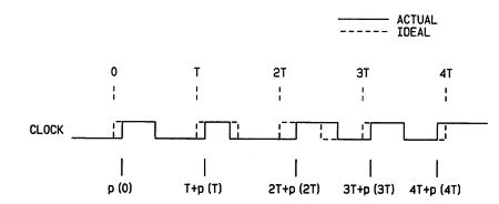 Fig.1 Jitter-free clock signal (solid) and with jitter (dashed).
Some systems look at only the rising edges, others the trailing edges of the data waveform. It is therefore necessary to examine clock jitter in terms of the relevant edges that affect system performance.
Jitter is very similar to a sampled voltage signal; both are a function of discrete time. Consequently, jitter can be expressed as a root-mean-square (RMS) value for the entire bandwidth, from 0Hz to the Nyquist frequency. This gives us an overall number to characterize the amount of jitter present.
It can be also defined for a given frequency band. It is more instructive, therefore, to express jitter in terms of its spectral distribution, either as picoseconds per square-root-Hertz, or as picoseconds per third-octave of bandwidth. Just as a sampled voltage spectrum can be manipulated and examined in a variety of ways, so too can a jitter spectrum be analyzed. Indeed, we will see that the jitter spectrum is of paramount importance, and that the overall RMS jitter figure conveys very little information.
How jitter affects converter performance
Fig.1 Jitter-free clock signal (solid) and with jitter (dashed).
Some systems look at only the rising edges, others the trailing edges of the data waveform. It is therefore necessary to examine clock jitter in terms of the relevant edges that affect system performance.
Jitter is very similar to a sampled voltage signal; both are a function of discrete time. Consequently, jitter can be expressed as a root-mean-square (RMS) value for the entire bandwidth, from 0Hz to the Nyquist frequency. This gives us an overall number to characterize the amount of jitter present.
It can be also defined for a given frequency band. It is more instructive, therefore, to express jitter in terms of its spectral distribution, either as picoseconds per square-root-Hertz, or as picoseconds per third-octave of bandwidth. Just as a sampled voltage spectrum can be manipulated and examined in a variety of ways, so too can a jitter spectrum be analyzed. Indeed, we will see that the jitter spectrum is of paramount importance, and that the overall RMS jitter figure conveys very little information.
How jitter affects converter performance
Jitter degrades digital audio system performance at the converters themselves, whether they are ADCs or DACs. If jitter is present in the sampling clock of an A/D converter, the sample values are taken either a little too early or a little too late. Similarly, clock jitter at a D/A converter causes the sample values to be converted to analog at the wrong times (figs.2 & 3). The result is distortion of the waveform and the creation of spurious components related to the jitter frequency.
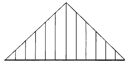 Fig.2 A/D conversion of a waveform with samples taken using a perfect sampling clock.
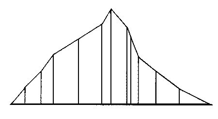 Fig.3 D/A reconstruction of the same waveform but using a jittered clock.
A distinction must be made between conventional multi-bit DACs ("R/2R" or "ladder" converters) and the so-called "1-bit" DACs that feature very high oversampling rates and noise shaping (footnote 4). Jitter affects these two converter types very differently.
A multi-bit DAC's analog output is a linear function of the input code; the larger the binary value input, the higher the analog output voltage (or current). A 1-bit DAC, however, outputs only a few discrete values (usually two), but changes state fast enough so that signal reconstruction can be realized with subsequent analog filtering. Examples of multi-bit DACs are the UltraAnalog D20400 and Burr-Brown PCM63. Common 1-bit DACs are the Crystal CS4328 and Philips SAA7350.
Because they are simpler, multi-bit converters are examined first. We'll assume the DAC is the conventional oversampling type, running at a clock frequency some multiple of the sampling rate (usually 352.8kHz, 8x the CD's 44.1kHz rate).
If the clock's edge occurs at the wrong time, the DAC's output will change at the same (wrong) time. If the clock edge occurs later than it should, the DAC's output changes level too late. Similarly, if the clock edge occurs early, the DAC's output changes level too soon. Both conditions cause an error in the analog signal output by the DAC. Because the time error is very small compared to the clock frequency, the error is a voltage pulse with an area equal to the time variation between when the edge should have occurred and when it actually occurred (the difference between a perfect clock and a jittered clock). This relationship between clock jitter, the DAC's output, and the resultant error is shown in fig.4.
Fig.3 D/A reconstruction of the same waveform but using a jittered clock.
A distinction must be made between conventional multi-bit DACs ("R/2R" or "ladder" converters) and the so-called "1-bit" DACs that feature very high oversampling rates and noise shaping (footnote 4). Jitter affects these two converter types very differently.
A multi-bit DAC's analog output is a linear function of the input code; the larger the binary value input, the higher the analog output voltage (or current). A 1-bit DAC, however, outputs only a few discrete values (usually two), but changes state fast enough so that signal reconstruction can be realized with subsequent analog filtering. Examples of multi-bit DACs are the UltraAnalog D20400 and Burr-Brown PCM63. Common 1-bit DACs are the Crystal CS4328 and Philips SAA7350.
Because they are simpler, multi-bit converters are examined first. We'll assume the DAC is the conventional oversampling type, running at a clock frequency some multiple of the sampling rate (usually 352.8kHz, 8x the CD's 44.1kHz rate).
If the clock's edge occurs at the wrong time, the DAC's output will change at the same (wrong) time. If the clock edge occurs later than it should, the DAC's output changes level too late. Similarly, if the clock edge occurs early, the DAC's output changes level too soon. Both conditions cause an error in the analog signal output by the DAC. Because the time error is very small compared to the clock frequency, the error is a voltage pulse with an area equal to the time variation between when the edge should have occurred and when it actually occurred (the difference between a perfect clock and a jittered clock). This relationship between clock jitter, the DAC's output, and the resultant error is shown in fig.4.
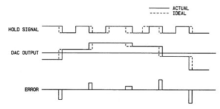 Fig.4 Error due to jitter at the output of a conventional (multi-bit) DAC.
These voltage pulses are filtered by the digital processor's analog filter, the playback electronics, loudspeakers, and the ear, resulting in unpleasant artifacts added to the music (footnote 5). Specifically, jitter with a frequency of 1kHz affecting a DAC reproducing a 7kHz sinewave will create spurious output tones at 6kHz and 8kHz. If the jitter has a frequency of 2kHz, the jitter-created artifacts will appear at 5kHz and 9kHz. These sidebands around the signal being decoded aren't harmonically related to the signal, making them particularly unpleasant. When the DAC is reproducing music (which has a constantly changing spectral content) and is controlled by a jittered clock (that may be jittered at several frequencies), the potential for generating a highly complex spectrum of jitter-induced spuriae is obvious. If the jitter is "white" (having a random spectral distribution rather than discrete frequency components), analog white noise will be added to the DAC's output signal.
Analysis reveals that the larger the signal and the higher its frequency, the more it is corrupted by clock jitter. Further, it is shown that in multi-bit converters, jitter above 40kHz can't intermodulate with DC-20kHz input signals to produce DC-20kHz artifacts. In other words, only jitter with a frequency below 40kHz can degrade the audio signal. This is a very important point, and one on which this discussion is based.
Fig.4 Error due to jitter at the output of a conventional (multi-bit) DAC.
These voltage pulses are filtered by the digital processor's analog filter, the playback electronics, loudspeakers, and the ear, resulting in unpleasant artifacts added to the music (footnote 5). Specifically, jitter with a frequency of 1kHz affecting a DAC reproducing a 7kHz sinewave will create spurious output tones at 6kHz and 8kHz. If the jitter has a frequency of 2kHz, the jitter-created artifacts will appear at 5kHz and 9kHz. These sidebands around the signal being decoded aren't harmonically related to the signal, making them particularly unpleasant. When the DAC is reproducing music (which has a constantly changing spectral content) and is controlled by a jittered clock (that may be jittered at several frequencies), the potential for generating a highly complex spectrum of jitter-induced spuriae is obvious. If the jitter is "white" (having a random spectral distribution rather than discrete frequency components), analog white noise will be added to the DAC's output signal.
Analysis reveals that the larger the signal and the higher its frequency, the more it is corrupted by clock jitter. Further, it is shown that in multi-bit converters, jitter above 40kHz can't intermodulate with DC-20kHz input signals to produce DC-20kHz artifacts. In other words, only jitter with a frequency below 40kHz can degrade the audio signal. This is a very important point, and one on which this discussion is based.
Footnote 1: At the time of writing this article, Rémy Fourré was Vice President of Engineering at UltraAnalog. Born and educated in France, Dr. Fourré earned the US equivalent of a Bachelor's degree in computer design, a Master's degree in electronics, a Ph.D. in mathematics and mechanics, and a Ph.D. in applied mechanics. Dr. Fourré joined the fledgling UltraAnalog in 1988, developing the company's high-resolution 20-bit A/D and D/A converters. He also designed the test and calibration instrumentation used in producing UltraAnalog DACs (see Stereophile, June '93, p.57). Before working in digital audio, Dr. Fourré helped design a failsafe computer architecture that is the basis for automatic pilot control of French passenger trains. He was awarded three patents for these efforts. His most recent work was designing UltraAnalog's AES 20 digital input receiver module, and instrumentation to measure jitter in the digital interface.—Robert Harley Footnote 2: See "The Jitter Game" in Vol.16 No.1 for a basic explanation of clock jitter.—Robert Harley Footnote 3: In its original form, this article presented the mathematical basis for the jitter calculations.—Robert Harley
Footnote 4: The same distinction applies to ADCs. Most audio ADCs today are noise-shaping (eg, the UltraAnalog ADC 20048, Crystal CS 5328, etc.).—Rémy Fourré
Footnote 5: Mathematically adept readers should note that the spectral distribution of these pulses after filtering is proportional to the convolution product of the input signal derivative spectrum by the jitter spectrum. This means that jitter of BHz affecting the clock of a DAC reproducing an AHz sinewave, for example, will cause output tones to appear at A+BHz and A-BHz. It also means that the larger the signal and the higher its frequency, the more it is affected by clock jitter.—Rémy Fourré
Jitter can be loosely defined as timing variations in the various sampling clocks used throughout a digital audio system. These timing variations affect the sampling clocks in professional A/D converters used to make CD master tapes, and the DAC clocks found in consumer digital processors and CD players. Although a Compact Disc or digital audio tape doesn't have jitter per se, the recorded digital data carries the effects of jitter produced by the ADC. The samples were taken at nonuniform time increments; when those samples are fed to a DAC with a uniform (jitter-free) clock, the sampled original analog signal is not accurately reconstructed. In a DAC fed samples taken at uniform time increments, jitter produces a similar skewing of the samples in time. Again, the reconstructed analog signal doesn't accurately represent the original audio signal.
Fig.1 Jitter-free clock signal (solid) and with jitter (dashed).
Some systems look at only the rising edges, others the trailing edges of the data waveform. It is therefore necessary to examine clock jitter in terms of the relevant edges that affect system performance.
Jitter degrades digital audio system performance at the converters themselves, whether they are ADCs or DACs. If jitter is present in the sampling clock of an A/D converter, the sample values are taken either a little too early or a little too late. Similarly, clock jitter at a D/A converter causes the sample values to be converted to analog at the wrong times (figs.2 & 3). The result is distortion of the waveform and the creation of spurious components related to the jitter frequency.
Fig.2 A/D conversion of a waveform with samples taken using a perfect sampling clock.
Fig.3 D/A reconstruction of the same waveform but using a jittered clock.
A distinction must be made between conventional multi-bit DACs ("R/2R" or "ladder" converters) and the so-called "1-bit" DACs that feature very high oversampling rates and noise shaping (footnote 4). Jitter affects these two converter types very differently.
A multi-bit DAC's analog output is a linear function of the input code; the larger the binary value input, the higher the analog output voltage (or current). A 1-bit DAC, however, outputs only a few discrete values (usually two), but changes state fast enough so that signal reconstruction can be realized with subsequent analog filtering. Examples of multi-bit DACs are the UltraAnalog D20400 and Burr-Brown PCM63. Common 1-bit DACs are the Crystal CS4328 and Philips SAA7350.
Because they are simpler, multi-bit converters are examined first. We'll assume the DAC is the conventional oversampling type, running at a clock frequency some multiple of the sampling rate (usually 352.8kHz, 8x the CD's 44.1kHz rate).
Fig.4 Error due to jitter at the output of a conventional (multi-bit) DAC.
These voltage pulses are filtered by the digital processor's analog filter, the playback electronics, loudspeakers, and the ear, resulting in unpleasant artifacts added to the music (footnote 5). Specifically, jitter with a frequency of 1kHz affecting a DAC reproducing a 7kHz sinewave will create spurious output tones at 6kHz and 8kHz. If the jitter has a frequency of 2kHz, the jitter-created artifacts will appear at 5kHz and 9kHz. These sidebands around the signal being decoded aren't harmonically related to the signal, making them particularly unpleasant. When the DAC is reproducing music (which has a constantly changing spectral content) and is controlled by a jittered clock (that may be jittered at several frequencies), the potential for generating a highly complex spectrum of jitter-induced spuriae is obvious. If the jitter is "white" (having a random spectral distribution rather than discrete frequency components), analog white noise will be added to the DAC's output signal.
Analysis reveals that the larger the signal and the higher its frequency, the more it is corrupted by clock jitter. Further, it is shown that in multi-bit converters, jitter above 40kHz can't intermodulate with DC-20kHz input signals to produce DC-20kHz artifacts. In other words, only jitter with a frequency below 40kHz can degrade the audio signal. This is a very important point, and one on which this discussion is based.
Footnote 1: At the time of writing this article, Rémy Fourré was Vice President of Engineering at UltraAnalog. Born and educated in France, Dr. Fourré earned the US equivalent of a Bachelor's degree in computer design, a Master's degree in electronics, a Ph.D. in mathematics and mechanics, and a Ph.D. in applied mechanics. Dr. Fourré joined the fledgling UltraAnalog in 1988, developing the company's high-resolution 20-bit A/D and D/A converters. He also designed the test and calibration instrumentation used in producing UltraAnalog DACs (see Stereophile, June '93, p.57). Before working in digital audio, Dr. Fourré helped design a failsafe computer architecture that is the basis for automatic pilot control of French passenger trains. He was awarded three patents for these efforts. His most recent work was designing UltraAnalog's AES 20 digital input receiver module, and instrumentation to measure jitter in the digital interface.—Robert Harley Footnote 2: See "The Jitter Game" in Vol.16 No.1 for a basic explanation of clock jitter.—Robert Harley Footnote 3: In its original form, this article presented the mathematical basis for the jitter calculations.—Robert Harley


