| Columns Retired Columns & Blogs |
Jitter & the Digital Interface Page 4
Jitter & the input receiver
Let's take a closer look at how the digital processor's input receiver affects the jitter at the DAC. First, the input receiver has an intrinsic jitter level, defined as the jitter on the recovered clock when the input signal is jitter-free. The amount of intrinsic jitter is the figure quoted by input receiver manufacturers (and by high-end companies using that receiver in their products) as the device's "jitter." For example, the popular Crystal CS8412 input receiver is quoted in the data sheet as having 200ps of jitter. The older Yamaha YM3623 input receiver has an intrinsic jitter level much higher than that of the Crystal.
Footnote 8: I found that the Audio Alchemy Digital Transmission Interface (DTI) did indeed improve or degrade the sound, depending on which combination of transport and processor it was used with. See my review in Vol.16 No.5.—Robert Harley
Let's take a closer look at how the digital processor's input receiver affects the jitter at the DAC. First, the input receiver has an intrinsic jitter level, defined as the jitter on the recovered clock when the input signal is jitter-free. The amount of intrinsic jitter is the figure quoted by input receiver manufacturers (and by high-end companies using that receiver in their products) as the device's "jitter." For example, the popular Crystal CS8412 input receiver is quoted in the data sheet as having 200ps of jitter. The older Yamaha YM3623 input receiver has an intrinsic jitter level much higher than that of the Crystal.
A more significant appraisal of input-receiver performance, however, is how well it rejects jitter in the incoming signal. Does the input receiver pass jitter from the transport to the recovered clock, or does it attenuate it? With well-designed transports and impedance-matched transmission lines, the intrinsic jitter dominates. But with poorly designed transports and impedance-mismatched transmission lines, the incoming jitter not rejected by the PLL becomes the dominant factor. The jitter in the recovered clock (what we're really concerned about) is thus a function of the transport's jitter, the interface-induced jitter, the input receiver's ability to reject incoming jitter, and the input receiver's intrinsic jitter.
By their nature, PLLs reject incoming jitter only above a certain frequency, called the jitter attenuation cutoff frequency. Consequently, we must consider both the receiver's intrinsic jitter and its jitter attenuation cutoff frequency when specifying an input receiver's performance. The single intrinsic jitter specification doesn't tell the whole story.
Barring design and layout errors, the jitter performance of a digital processor is primarily dependent on the input receiver stage. The best currently available monolithic (chip) input receiver is the Crystal CS8412. This has an intrinsic jitter of 200ps and a jitter attenuation cutoff frequency of 25kHz. With no input signal, the CS8412 will introduce 200ps of clock jitter. Jitter in the incoming data stream with a frequency below 25kHz will be passed to the recovered clock. The performance achieved by the best currently available hybrid digital audio receiver (UltraAnalog AES 20) is typically 40ps for intrinsic jitter and 1kHz for jitter attenuation cutoff frequency.
These criteria for specifying input receiver performance also apply to "reclocking" devices that claim to reduce jitter in the data signal. These devices receive an AES/EBU or S/PDIF input signal, recover the clock from this signal, and reclock the output signal with this improved clock. Just as with an input receiver, we want to know the device's intrinsic jitter and its jitter attenuation cutoff frequency. A reclocker can only be as good as the input receiver it uses.
Reclockers have two major limitations. First, if the CD transport's intrinsic jitter is less than the reclocker's intrinsic jitter (in the DC-40kHz band), the reclocker can only add jitter. A reclocker can improve high-jitter transports, but it degrades low-jitter transports (footnote 8). Although the output clock may appear much cleaner on an oscilloscope when high-frequency jitter is attenuated, it doesn't mean there is less jitter in the DC-40kHz band. Remember, only jitter in this band can affect a multi-bit converter's sonic performance. Only a spectral analysis of the jitter can reveal whether these devices improve or degrade the signal.
The second limitation of reclocking devices is the reclocker's jitter attenuation cutoff frequency. If it isn't lower than that of the digital processor's input receiver, the reclocker will simply pass incoming jitter at frequencies which will be rejected anyway by the digital processor's input receiver.
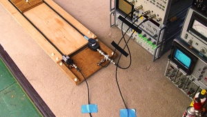
Using the UltraAnalog-designed and -built jitter analyzer described earlier, we measured the jitter present on the AES/EBU and S/PDIF outputs of several CD transports. Large differences were found in these products' jitter performance. Fig.10 is the jitter spectrum and level of a low-jitter transport; fig.11 is the jitter spectrum and level of a high-jitter transport.
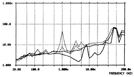
Fig.10 Spectrum of a good transport's intrinsic jitter in pause (19.3ps, solid line); while playing CBS CD-1, track 1, 1kHz at 0dBFS (35.9ps, long-dashed line); playing CBS CD-1, track 5, 1kHz at -60dBFS (63.1ps, short-dashed line); and playing CBS CD-1, track 13, 60Hz+7kHz in a 4:1 mix at 0dBFS (35.4ps, dotted line) (vertical scale is ps per 1/3-octave band).
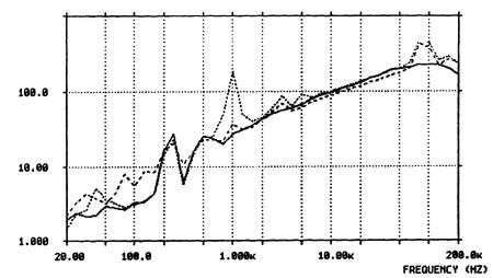
Fig.11 Spectrum of a poor transport's intrinsic jitter in pause (394.4ps, solid line); while playing CBS CD-1, track 1, 1kHz at 0dBFS (358.6ps, long-dashed line); playing CBS CD-1, track 5, 1kHz at -60dBFS (456.6ps, dotted line) (vertical scale is ps per 1/3-octave band).
Because the jitter is correlated with the digital input signal, the jitter amount and spectrum vary with the test signal. Consequently, jitter is plotted with different input signals, specified in the captions. The peak at 1kHz in both plots is signal-correlated jitter. The peak at 7.35kHz is a result of the 7.35kHz subcode data rate within the S/PDIF signal, and the peaks at 44.1kHz and 88.2kHz result from the frame and preamble structure of the S/PDIF interface signal. Because these last two components are above 40kHz, they do not produce sonic degradation.
The good transport's measured performance is very close to the analyzer's noise floor, emphasizing that it is easier to build a low-jitter transmitter than a low-jitter receiver. There is no excuse for designing a jittery transport. Although not apparent on the plots, the poor transport is plagued by repetitive jitter pulses of 3000ps amplitude. The pulses are about 20µs wide, with a repetition rate of 229.6875Hz, the block rate of the S/PDIF signal. The poor transport's jitter also varies with temperature, line-input voltage, and other factors.
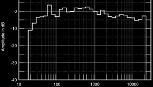
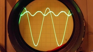
The analyzer output can be plotted as a function of frequency (as shown in figs.10 and 11), looked at on an oscilloscope, input to an FFT machine, or listened to through a playback system. This last option allows us to hear the jitter from different transports and digital sources. The correlation between the audio signal and the jitter is so high that the music is easily recognized just by listening to the jitter. When playing a swept sinewave, beat patterns between the signal and the 44.1kHz sampling frequency are easily audible. Clearly, the jitter analyzer is a powerful tool for investigating the jitter performance of digital sources and input receiver circuits (footnote 9).
Conclusion
Thanks to papers presented at AES conventions and articles in Stereophile, consumers are becoming increasingly aware of jitter and how it degrades digitally reproduced music. The vast range of jitter performance among commercially available transports suggests that manufacturers need to address this problem. Transports should be specified by the amount of jitter in their outputs in the DC-40kHz range. Similarly, input receivers used in digital processors should be specified for intrinsic jitter and their jitter attenuation cutoff frequency.
By combining a theoretical understanding of jitter with a practical measurement instrument and new circuit designs, jitter need no longer be the hidden source of degradation in digitally reproduced music.
Footnote 8: I found that the Audio Alchemy Digital Transmission Interface (DTI) did indeed improve or degrade the sound, depending on which combination of transport and processor it was used with. See my review in Vol.16 No.5.—Robert Harley
Footnote 9: UltraAnalog made its jitter analyzer available to Stereophile for testing transports, interfaces, and jitter-reduction devices. Robert Harley used it to measure all the transports he could get his hands on for a report in the November 1993 issue. He also looked at the Audio Alchemy DTI's effect on data-stream jitter measured jitter differences in different cables and interfaces.—John Atkinson
|
| |||||||||
- Log in or register to post comments


| Loudspeakers Amplification Digital Sources | Analog Sources Accessories Featured | Music Columns Retired Columns | Show Reports | Features Latest News Community | Resources Subscriptions |
 © 2024 Stereophile
AVTech Media Americas Inc., USA
All rights reserved

