"How sour sweet music is
When time is broke and no proportion kept!" With those lines from Richard II, Shakespeare unwittingly described a phenomenon in digital audio called "word clock jitter" and its detrimental effect on digitally reproduced music. "Clock jitter" refers to timing errors in analog/digital and digital/analog converters—errors that significantly degrade the musical quality of digital audio. Clock jitter is a serious and underestimated source of sonic degradation in digital audio. Only recently has jitter begun to get the attention it deserves, both by high-end designers and audio academics. One reason jitter has been overlooked is the exceedingly difficult task of measuring such tiny time variations—on the order of tens of trillionths of a second. Consequently, there has previously been little hard information on how much jitter is actually present in high-end D/A converters. This is true despite the "jitter wars" between manufacturers who claim extraordinarily low jitter levels in their products. Another reason jitter has been ignored is the mistaken belief by some that if the ones and zeros that represent the music are correct, then digital audio must work perfectly. Getting the ones and zeros correct is only part of the equation. Stereophile has obtained a unique instrument that allows us to measure jitter in CD players and digital processors. Not only can we quantify how much jitter is afflicting a particular D/A converter, we can look at something far more musically relevant: the jitter's frequency. Moreover, an analysis of jitter and what causes it goes a long way toward explaining the audible differences between CD transports, digital processors, and, particularly, the type of interface between transport and processor.
This article presents a basic primer on word clock jitter, explains how it affects the musical performance of digital processors, and reports the results of an investigation into the jitter performances of 11 high-end digital processors and one CD player. In addition, we are able—for the first time—to measure significant differences in jitter levels and spectra between different types of CD transport/digital processor interfaces.
We have found a general correlation between a digital processor's jitter performance and certain aspects of its musical presentation. The jitter measurements presented in this article were made on processors with whose sound I was familiar; in preparation for their reviews, each had been auditioned at matched levels for at least three weeks in my reference playback system. Because the reviews of these processors have already been published, it's possible to compare the musical impressions reported to the processors' jitter performance. Although these jitter measurements are far from the last word in quantifying a digital processor's musical performance, there is nevertheless a trend that suggests a correlation between listening and measurement.
This article will also attempt to dispel the popular notion that "bits is bits." This belief holds that if the ones and zeros in a digital audio system are the same, the sound will be the same. Proponents of this position like to draw the analogy of putting money in the bank: "your money," though merely a digital representation on magnetic tape, remains inviolate (you hope). There's a problem with this argument, however: unlike the bank's digital record on magnetic tape, digital audio data is useful only after it is converted to analog. And here is where the variability occurs. Presenting the correct ones and zeros to the DAC is only half the battle; those ones and zeros must be converted to analog with incredibly precise timing to avoid sonic degradation.
As we shall see, converting digitally represented music into analog—a process somewhat akin to turning ground beef back into steak—is far more complex and exacting than had been realized.
Sampling
To understand how even small amounts of clock jitter can have a large effect on the analog output signal, a brief tutorial on digital audio sampling is helpful. Sampling is the process of converting a continuous event into a series of discrete events. In an analog-to-digital (A/D) converter, the continuously varying voltage that represents the analog waveform is "looked at" (sampled) at precise time intervals. In the case of the Compact Disc's 44.1kHz sampling rate, the A/D converter samples the analog waveform 44,100 times per second. For each sample, a number is assigned that represents the amplitude of the analog waveform at the sample time. This number, expressed in binary form (one or zero) and typically 16 bits long, is called a "word." The process of converting the analog signal's voltage into a value represented by a binary word is called "quantization," the effectively infinite range of values allowable in an analog system being reduced to a limited number of discrete amplitudes. Any analog value falling between two binary values is represented by the nearest one.
Sampling and quantization are the foundation of digital audio; sampling preserves the time information (as long as the sampling frequency is more than twice the highest frequency present in the analog signal) and quantization preserves the amplitude information (with a fundamental error equal to half the amplitude difference between two adjacent binary values). We won't worry about quantization here—it's the sampling process we need to understand.
The series of discrete samples generated by the A/D converter can be converted back into a continuously varying signal with a D/A converter (DAC). A DAC takes a digital word and outputs a voltage equivalent to that word, exactly the opposite function of the A/D converter (ADC). All that is required for perfect conversion (in the time domain) is that the samples be input to the DAC in the same order they were taken, and with the same timing reference. In theory, this sounds easy—just provide a stable 44.1kHz clock to the A/D converter and a stable 44.1kHz clock to the D/A converter. Voilà!—perfect digital audio.
Clock jitter
Unfortunately, it isn't that easy in practice. If the samples don't generate an analog waveform with the identical timing with which they were taken, distortion will result. These timing errors between samples are caused by variations in the clock signal that controls when the DAC converts each digital word to an analog voltage.
Let's take a closer look at how the DAC decides when to convert the digital samples to analog. In fig.1, the binary number at the left is the quantization word that represents the analog waveform's amplitude when first sampled. The bigger the number, the higher the amplitude. (This is only conceptually true—in practice the data are in twos-complement form, which uses the most significant bit or MSB at the start of the word as a sign bit, a "1" meaning that the amplitude is negative.)
 Fig.1 The word-clock signal triggers the DAC to output an analog voltage equivalent to the input digital word.
The squarewave at the top of fig.1 is the "word clock," the timing signal that tells the DAC when to convert the quantization word to an analog voltage. Assuming the original sampling frequency was 44.1kHz, the word clock's frequency will also be 44.1kHz (or some multiple of 44.1kHz if the processor uses an oversampling digital filter). On the word clock's leading edge, the next sample (quantization word) is loaded into the DAC. On the word clock's falling edge, the DAC converts that quantization word to an analog voltage. This process happens 44,100 times per second (without oversampling). If the digital processor has an 8x-oversampling digital filter, the word-clock frequency will be eight times 44,100, or 352.8kHz.
It is here at the word clock that timing variations affect the analog output signal. Specifically, clock jitter is any time variation between the clock's trailing edges. Fig.2 shows a perfect clock and a jittered clock (exaggerated for clarity) (footnote 1).
Fig.1 The word-clock signal triggers the DAC to output an analog voltage equivalent to the input digital word.
The squarewave at the top of fig.1 is the "word clock," the timing signal that tells the DAC when to convert the quantization word to an analog voltage. Assuming the original sampling frequency was 44.1kHz, the word clock's frequency will also be 44.1kHz (or some multiple of 44.1kHz if the processor uses an oversampling digital filter). On the word clock's leading edge, the next sample (quantization word) is loaded into the DAC. On the word clock's falling edge, the DAC converts that quantization word to an analog voltage. This process happens 44,100 times per second (without oversampling). If the digital processor has an 8x-oversampling digital filter, the word-clock frequency will be eight times 44,100, or 352.8kHz.
It is here at the word clock that timing variations affect the analog output signal. Specifically, clock jitter is any time variation between the clock's trailing edges. Fig.2 shows a perfect clock and a jittered clock (exaggerated for clarity) (footnote 1).
 Fig.2 Word-clock jitter consists either of a random variation in the pulse timing or a variation which itself has a periodic component.
Now, look what happens if the samples are reconstructed by a DAC whose word clock is jittered (fig.3). The sample amplitudes—the ones and zeros—are correct, but they're in the wrong place! The right amplitude at the wrong time is the wrong amplitude. A time variation in the word clock produces an amplitude variation in the output, causing the waveform to change shape. A change in shape of a waveform is the very definition of distortion. Remember, the word clock tells the DAC when to convert the audio sample to an analog voltage; any variations in its accuracy will produce an analog-like variability in the final output signal—the music.
Fig.2 Word-clock jitter consists either of a random variation in the pulse timing or a variation which itself has a periodic component.
Now, look what happens if the samples are reconstructed by a DAC whose word clock is jittered (fig.3). The sample amplitudes—the ones and zeros—are correct, but they're in the wrong place! The right amplitude at the wrong time is the wrong amplitude. A time variation in the word clock produces an amplitude variation in the output, causing the waveform to change shape. A change in shape of a waveform is the very definition of distortion. Remember, the word clock tells the DAC when to convert the audio sample to an analog voltage; any variations in its accuracy will produce an analog-like variability in the final output signal—the music.
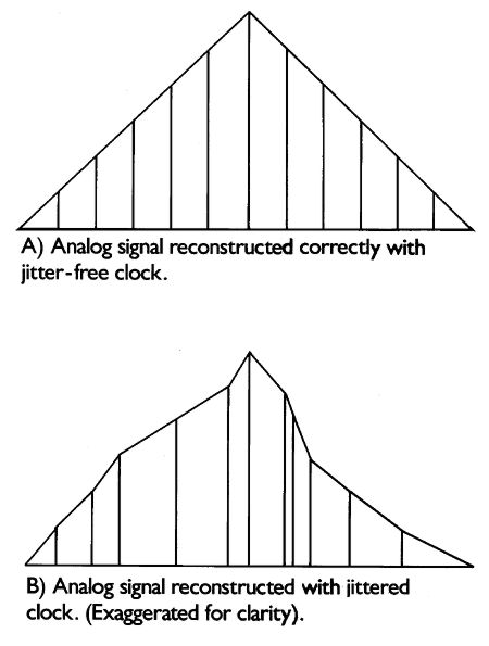 Fig.3 Analog waveform is constructed correctly with a jitter-free word clock (top); word-clock jitter results in a distortion of the analog waveform's shape (exaggerated for clarity).
Footnote 1 :Although some DACs convert on the leading edge, most convert on the trailing edge. Whichever type is used, the effects of jitter are identical.—Robert Harley
When time is broke and no proportion kept!" With those lines from Richard II, Shakespeare unwittingly described a phenomenon in digital audio called "word clock jitter" and its detrimental effect on digitally reproduced music. "Clock jitter" refers to timing errors in analog/digital and digital/analog converters—errors that significantly degrade the musical quality of digital audio. Clock jitter is a serious and underestimated source of sonic degradation in digital audio. Only recently has jitter begun to get the attention it deserves, both by high-end designers and audio academics. One reason jitter has been overlooked is the exceedingly difficult task of measuring such tiny time variations—on the order of tens of trillionths of a second. Consequently, there has previously been little hard information on how much jitter is actually present in high-end D/A converters. This is true despite the "jitter wars" between manufacturers who claim extraordinarily low jitter levels in their products. Another reason jitter has been ignored is the mistaken belief by some that if the ones and zeros that represent the music are correct, then digital audio must work perfectly. Getting the ones and zeros correct is only part of the equation. Stereophile has obtained a unique instrument that allows us to measure jitter in CD players and digital processors. Not only can we quantify how much jitter is afflicting a particular D/A converter, we can look at something far more musically relevant: the jitter's frequency. Moreover, an analysis of jitter and what causes it goes a long way toward explaining the audible differences between CD transports, digital processors, and, particularly, the type of interface between transport and processor.
To understand how even small amounts of clock jitter can have a large effect on the analog output signal, a brief tutorial on digital audio sampling is helpful. Sampling is the process of converting a continuous event into a series of discrete events. In an analog-to-digital (A/D) converter, the continuously varying voltage that represents the analog waveform is "looked at" (sampled) at precise time intervals. In the case of the Compact Disc's 44.1kHz sampling rate, the A/D converter samples the analog waveform 44,100 times per second. For each sample, a number is assigned that represents the amplitude of the analog waveform at the sample time. This number, expressed in binary form (one or zero) and typically 16 bits long, is called a "word." The process of converting the analog signal's voltage into a value represented by a binary word is called "quantization," the effectively infinite range of values allowable in an analog system being reduced to a limited number of discrete amplitudes. Any analog value falling between two binary values is represented by the nearest one.
Unfortunately, it isn't that easy in practice. If the samples don't generate an analog waveform with the identical timing with which they were taken, distortion will result. These timing errors between samples are caused by variations in the clock signal that controls when the DAC converts each digital word to an analog voltage.
Fig.1 The word-clock signal triggers the DAC to output an analog voltage equivalent to the input digital word.
The squarewave at the top of fig.1 is the "word clock," the timing signal that tells the DAC when to convert the quantization word to an analog voltage. Assuming the original sampling frequency was 44.1kHz, the word clock's frequency will also be 44.1kHz (or some multiple of 44.1kHz if the processor uses an oversampling digital filter). On the word clock's leading edge, the next sample (quantization word) is loaded into the DAC. On the word clock's falling edge, the DAC converts that quantization word to an analog voltage. This process happens 44,100 times per second (without oversampling). If the digital processor has an 8x-oversampling digital filter, the word-clock frequency will be eight times 44,100, or 352.8kHz.
Fig.2 Word-clock jitter consists either of a random variation in the pulse timing or a variation which itself has a periodic component.
Now, look what happens if the samples are reconstructed by a DAC whose word clock is jittered (fig.3). The sample amplitudes—the ones and zeros—are correct, but they're in the wrong place! The right amplitude at the wrong time is the wrong amplitude. A time variation in the word clock produces an amplitude variation in the output, causing the waveform to change shape. A change in shape of a waveform is the very definition of distortion. Remember, the word clock tells the DAC when to convert the audio sample to an analog voltage; any variations in its accuracy will produce an analog-like variability in the final output signal—the music.
Fig.3 Analog waveform is constructed correctly with a jitter-free word clock (top); word-clock jitter results in a distortion of the analog waveform's shape (exaggerated for clarity).
Footnote 1 :Although some DACs convert on the leading edge, most convert on the trailing edge. Whichever type is used, the effects of jitter are identical.—Robert Harley