| Columns Retired Columns & Blogs |
The Jitter Game The Jitter Game: an Update, October 1993
The Jitter Game: an Update, October 1993 (Vol.16 No.10):
Since last January's "The Jitter Game," Stereophile has been able to measure and report on clock jitter in digital processors and CD players under review. In the intervening nine months, the technique has been improved with a second-generation Meitner LIM Detector (the jitter-measurement instrument), more sensitive measurement methods, and improved interpretation of the results.
First, Ed Meitner redesigned the LIM Detector. He added a "phase-detected" output that integrates the jitter, producing a flatter output with frequency. The original LIM Detector had a 6dB/octave rise with increasing frequency. Although this is a valid approach, the new LIM Detector has both phase and frequency outputs. Ed also reduced the power-supply noise, lowered the test instrument's noise floor, and generally improved the circuit. The new version works exactly as the first one, on a theoretical basis.
Second, we've changed the scale on the jitter FFT plots. A general consensus is emerging that 0dBR should equal one nanosecond (1ns) rather than the 226.8ns we chose for the first article. Note that FFT plots show a lower floor than if we had measured the RMS jitter with 1/3-octave spectral analysis. When the trace appears at a lower level (-60dBR instead of -40dBR, for example), we know that the processor with a trace at -60 has lower jitter. But we can't reference that level to 0dBR=1ns and conclude that a trace at -40dBR is 40dB below 1ns (100 times less than 1ns, or 10ps). It's analogous to measuring amplifier distortion as an RMS THD+N figure vs performing an FFT on the discrete harmonic products.
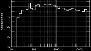
Third, we've switched to using a PS Audio Lambda transport to drive the digital processors under test. All previous measurements were taken with a JVC XLZ-1010. Figs.1 and 2 show the Reference Link's jitter spectrum when driven by the JVC and by the Lambda, respectively. Although the RMS level appears slightly lower with the JVC, the Lambda clearly has fewer discrete-frequency jitter components and a much cleaner spectrum. Since it's the digital-processor clock jitter we're trying to measure, it makes sense to drive it with a low-jitter source to isolate the processor's jitter from the transport's jitter. It's interesting to note, from figs.1 and 2, that the Crystal CS8412 input receiver used in the Reference Link passes the transport's audio-band jitter through to the recovered clock.
Fourth, we've increased the measurement technique's sensitivity by band-limiting the data. We used to read the overall RMS jitter level as a voltage on an RMS-reading voltmeter—the meter reads the LIM Detector's rising noise floor at low frequencies (seen as the rise below 1kHz in figs.1 and 2). This technique didn't differentiate between jitter and noise. In the new method of determining the RMS jitter level, the data file from the FFT is called into an ASCII text editor (a word-processing program), and all the data points below 950Hz are thrown out. These points are still plotted on the graph, but are removed when calculating the RMS jitter value. Another program then computes the average level of the remaining data points. The result is a more accurate reflection of the processor's jitter.

Fig.1 PS Audio Reference Link, word-clock jitter spectrum, DC-20kHz, when processing 1kHz sinewave at 0dBFS from JVC XL-Z1010 transport (linear frequency scale, 10dB/vertical div., 0dB = 1ns).

Fig.2 PS Audio Reference Link, word-clock jitter spectrum, DC-20kHz, when processing 1kHz sinewave at 0dBFS from PS Audio Lambda transport (linear frequency scale, 10dB/vertical div., 0dB = 1ns).
While we're on the subject of bandwidth, I should point out that the LIM Detector has an upper cutoff frequency of 20kHz, while jitter up to 40kHz is sonically degrading (see Rémy Fourré's article in this issue). The LIM Detector thus measures only half the relevant bandwidth. Although this is a limitation, it isn't a significant one. If we see lots of spikes in the trace in the DC-20kHz band, we can reasonably conclude that the product has worse jitter performance than a processor with a clean trace in the DC-20kHz band. Moreover, it's unlikely that the jitter level or character (white jitter or periodic jitter) will change significantly in the 20kHz-40kHz band.
Finally, we can also remove the LIM Detector's noise floor from the jitter calculations, leaving only the jitter level of the digital processor under test. When two uncorrelated noise sources (the LIM Detector and the processor under test) are added, the total noise is the square root of the sum of the squares of the individual noise sources. Because we know the total jitter and the LIM Detector's intrinsic jitter, we can calculate the jitter of the device under test.
A general engineering principle holds that a measurement instrument's noise should be ten times lower than the device you're trying to measure. This is the ideal; in practice, three times is more realistic. With the LIM Detector measuring the very lowest-jitter processors, however, the LIM Detector's intrinsic jitter is below that of the processor, but doesn't meet the three-times rule. With most processors, the LIM Detector's noise floor is at least five times lower than that of the device under test.
The jitter measurements presented in this issue's Reference Link review are the first using these new methods. Note that they are not directly comparable to previous jitter measurements. But now that we've settled on these refined techniques, we can report with greater precision the jitter performance of digital processors and CD players.—Robert Harley
|
| |||||||||
- Log in or register to post comments


| Loudspeakers Amplification Digital Sources | Analog Sources Accessories Featured | Music Columns Retired Columns | Show Reports | Features Latest News Community | Resources Subscriptions |
 © 2024 Stereophile
AVTech Media Americas Inc., USA
All rights reserved

