Sidebar 3: Measurements
To precondition an amplifier before testing, I run it at one-third power into 8 ohms for an hour, which thermally stresses an amplifier with a class-B output stage to the maximum extent. While the Yamaha's top panel was faintly warm to the touch after this period, the efficiency of its class-D output circuitry means that very little power was being wasted as heat.
Measuring the Yamaha MX-D1 was complicated by the fact that, even with an internal low-pass filter between each output stage and the speaker terminals, there will be a relatively high level of RF switching noise present at the switching frequency and its harmonics that ride on the amplified audio signal. This noise can adversely but misleadingly influence such an amplifier's measured performance because it can drive the input stage of the test gear into slew-rate limiting. As explained by analog test maven Bruce Hofer in "Measuring Switch-mode Power Amplifiers," a white paper that can be downloaded from the Audio Precision website, "all commercial audio analyzers employ precision low noise and distortion [op-amps] in their input and signal processing stages. These devices have typical slew rate capabilities of only 5–10V/µs. . . . Within the current state-of-the-art, it is simply not possible to design a high impedance analog input stage having audio-worthy distortion and noise performance without incurring a practical slew rate limitation."
Audio Precision sells a precision passive low-pass filter to be used between the output of an amplifier with a class-D output stage and an Audio Precision analyzer. Unfortunately, I have not yet upgraded my test system with one of these filters, so to examine the MX-D1's performance at low signal levels, I used an active sixth-order low-pass filter with a 20kHz bandwidth and a floating input. My high-level tests were taken with the amplifier driving the System One directly, so I caution readers (and Yamaha) not to take the specific graphs as representing anything more than broad-brush pictures of the amplifier's behavior.
Although the MX-D1 features XLR jacks for balanced drive, these didn't appear to be functional on our sample. I ran tests using only the unbalanced RCA jacks, therefore. The Yamaha MX-D1 offered a significantly higher-than-usual voltage gain, at 33.9dB into 8 ohms. Its input impedance measured 24k ohms across the audioband, and it preserved signal polarity; ie, was noninverting. Its output impedance (including 6' of multistrand cable) was a low 0.07 ohm in the midrange and bass, rising to 0.45 ohm at 20kHz due to the presence of the necessary internal output filtering.
While the MX-D1's low source impedance over most of the audioband means it suffers from very little modification of its frequency response due to the usual Ohm's Law interaction between that impedance and the manner in which the load impedance changes with frequency (fig.1, top dashed trace at 2kHz), the presence of an internal filter means that there will be some ultrasonic response peaking evident. This can be seen in fig.1, all the traces showing a narrow peak at 67.3kHz. However, fig.1 also shows that the height of this peak depends on the load impedance, the peak becoming increasingly suppressed as the impedance decreases. However, the Yamaha's bandwidth also decreases with decreasing load impedance; flat to 20kHz into 8 ohms, it is –1.8dB at 20kHz into 2 ohms, presumably due to the increasing source impedance at high frequencies.
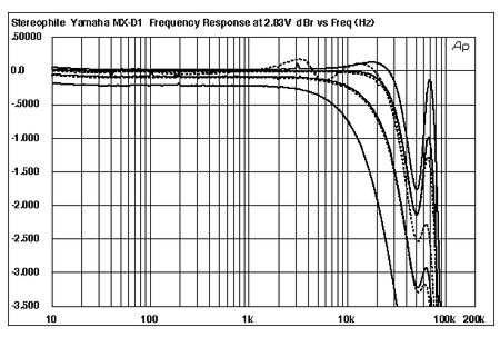 Fig.1 Yamaha MX-D1, frequency response at 2.83V into (from top to bottom at 2kHz): simulated loudspeaker load, 16 ohms, 8 ohms, 4 ohms, 2 ohms (0.5dB/vertical div., right channel dashed).
The presence of this ultrasonic peak makes its presence felt on the amplifier's reproduction of a 10kHz squarewave (fig.2) as a small degree of overshoot and some damped ringing. However, I feel this is nothing to be concerned about.
Fig.1 Yamaha MX-D1, frequency response at 2.83V into (from top to bottom at 2kHz): simulated loudspeaker load, 16 ohms, 8 ohms, 4 ohms, 2 ohms (0.5dB/vertical div., right channel dashed).
The presence of this ultrasonic peak makes its presence felt on the amplifier's reproduction of a 10kHz squarewave (fig.2) as a small degree of overshoot and some damped ringing. However, I feel this is nothing to be concerned about.
 Fig.2 Yamaha MX-D1, small-signal 10kHz squarewave into 8 ohms.
Channel separation (not shown), assessed with the external small-signal low-pass filter, was both superb and to specification, at 100dB at 1kHz in both directions. The A-weighted signal/noise ratio was also superb, at 82.2dB ref. 1W into 8 ohms, 110dB ref. clipping into the same load. No wonder Michael Fremer was impressed by the amplifier's "blackest backdrops." However, because of the ultrasonic switching noise present in the amplifier's output, this figure worsened to just 27.8dB using an unweighted measurement with a 500kHz bandwidth.
This RF noise can be seen in the distortion and noise waveform taken while the amplifier was driving a 1kHz tone at 6W into 8 ohms (fig.3). The measured THD+noise level was 0.3%, but as this graph shows, that figure is due to noise. Inserting the external low-pass filter between the amplifier's output and the Audio Precision analyzer's input gave the waveform shown in fig.4. With the ultrasonic noise eliminated, the THD+N level has dropped to 0.0176%, which is very respectable, if not quite as low as the 0.003% specified by Yamaha. The distortion appears to be heavily third-harmonic in nature. Decreasing the load impedance didn't affect the amount of distortion, but its spectrum shifted toward a mix of second-harmonic distortion overlaid by higher-order harmonics (not shown).
Fig.2 Yamaha MX-D1, small-signal 10kHz squarewave into 8 ohms.
Channel separation (not shown), assessed with the external small-signal low-pass filter, was both superb and to specification, at 100dB at 1kHz in both directions. The A-weighted signal/noise ratio was also superb, at 82.2dB ref. 1W into 8 ohms, 110dB ref. clipping into the same load. No wonder Michael Fremer was impressed by the amplifier's "blackest backdrops." However, because of the ultrasonic switching noise present in the amplifier's output, this figure worsened to just 27.8dB using an unweighted measurement with a 500kHz bandwidth.
This RF noise can be seen in the distortion and noise waveform taken while the amplifier was driving a 1kHz tone at 6W into 8 ohms (fig.3). The measured THD+noise level was 0.3%, but as this graph shows, that figure is due to noise. Inserting the external low-pass filter between the amplifier's output and the Audio Precision analyzer's input gave the waveform shown in fig.4. With the ultrasonic noise eliminated, the THD+N level has dropped to 0.0176%, which is very respectable, if not quite as low as the 0.003% specified by Yamaha. The distortion appears to be heavily third-harmonic in nature. Decreasing the load impedance didn't affect the amount of distortion, but its spectrum shifted toward a mix of second-harmonic distortion overlaid by higher-order harmonics (not shown).
 Fig.3 Yamaha MX-D1, no external low-pass filter, 1kHz waveform at 6W into 8 ohms (top), 0.3% THD+N; distortion and noise waveform with fundamental notched out (bottom, not to scale).
 Fig.4 Yamaha MX-D1, with external sixth-order low-pass filter, 20kHz bandwidth, 1kHz waveform at 6W into 8 ohms (top), 0.0176% THD+N; distortion and noise waveform with fundamental notched out (bottom, not to scale).
Because of the 20kHz filter I was using, I couldn't plot the THD+N percentage against frequency for signals greater than 10kHz (the second harmonic of a 10kHz tone lies at 20kHz). But I did so up to that frequency into loads ranging from 2 ohms to 16 ohms (fig.5). The distortion is respectably low into loads of 4 ohms and below, though it does increase by a factor of four into 2 ohms. It also rises in the treble, though not to a subjectively significant degree. (The apparent decrease in distortion above 6kHz is due to the low-pass filter starting to roll off the third- and higher-order harmonics and should be disregarded.)
Fig.4 Yamaha MX-D1, with external sixth-order low-pass filter, 20kHz bandwidth, 1kHz waveform at 6W into 8 ohms (top), 0.0176% THD+N; distortion and noise waveform with fundamental notched out (bottom, not to scale).
Because of the 20kHz filter I was using, I couldn't plot the THD+N percentage against frequency for signals greater than 10kHz (the second harmonic of a 10kHz tone lies at 20kHz). But I did so up to that frequency into loads ranging from 2 ohms to 16 ohms (fig.5). The distortion is respectably low into loads of 4 ohms and below, though it does increase by a factor of four into 2 ohms. It also rises in the treble, though not to a subjectively significant degree. (The apparent decrease in distortion above 6kHz is due to the low-pass filter starting to roll off the third- and higher-order harmonics and should be disregarded.)
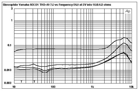 Fig.5 Yamaha MX-D1, left channel only with external sixth-order low-pass filter, 20kHz bandwidth, THD+N (%)vs frequency at 5V into (from bottom to top): 16 ohms, 8 ohms, 4 ohms, 2 ohms.
As I said earlier, the active nature of the low-pass filter I was using meant I couldn't use it for high-level testing. The two following graphs therefore include both high-frequency noise and possibly a contribution from the Audio Precision's input stage. They should not be taken as representing the Yamaha's absolute performance, therefore, but are interesting nevertheless. Fig.6 is the spectrum of the amplifier's output while it drove a 50Hz tone into 4 ohms. The power was moderately high; even so, the distortion harmonics all lie at –80dB or below. The Yamaha is obviously a very linear design.
Fig.5 Yamaha MX-D1, left channel only with external sixth-order low-pass filter, 20kHz bandwidth, THD+N (%)vs frequency at 5V into (from bottom to top): 16 ohms, 8 ohms, 4 ohms, 2 ohms.
As I said earlier, the active nature of the low-pass filter I was using meant I couldn't use it for high-level testing. The two following graphs therefore include both high-frequency noise and possibly a contribution from the Audio Precision's input stage. They should not be taken as representing the Yamaha's absolute performance, therefore, but are interesting nevertheless. Fig.6 is the spectrum of the amplifier's output while it drove a 50Hz tone into 4 ohms. The power was moderately high; even so, the distortion harmonics all lie at –80dB or below. The Yamaha is obviously a very linear design.
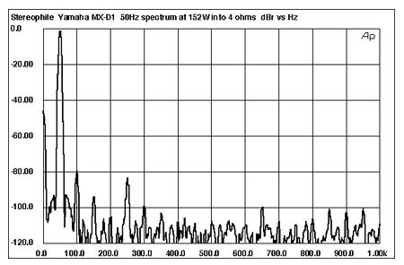 Fig.6 Yamaha MX-D1, no low-pass filter, spectrum of 50Hz sinewave, DC–1kHz, at 152W into 4 ohms (linear frequency scale).
I haven't shown the high-frequency intermodulation result because I wasn't confident that I was getting an accurate picture of the amplifier's behavior. For a start, there seemed to be some interaction between the amplifier and the signal, in that I couldn't reach true clipping with this signal due to the amplifier appearing to reduce its gain at very high powers before I could do so. Even so, at 200W peak into 8 ohms, the 1kHz difference tone lay at –70dB, which is still low.
Finally, fig.7 shows how the percentage of THD+N in the MX-D1's output changes with output power into 16, 8, 4, and 2 ohms. Below 100W, the downward slope of these traces is due to the measured figure being dominated by the switching noise. However, the actual clipping point is clearly defined. This small amplifier is surprisingly powerful. Defining clipping as 1% THD+N, it delivered 530W into 8 ohms (27.25dBW) and 590W into 4 ohms (24.7dBW), faltering slightly into 2 ohms, with 478W available (20.8dBW).
Fig.6 Yamaha MX-D1, no low-pass filter, spectrum of 50Hz sinewave, DC–1kHz, at 152W into 4 ohms (linear frequency scale).
I haven't shown the high-frequency intermodulation result because I wasn't confident that I was getting an accurate picture of the amplifier's behavior. For a start, there seemed to be some interaction between the amplifier and the signal, in that I couldn't reach true clipping with this signal due to the amplifier appearing to reduce its gain at very high powers before I could do so. Even so, at 200W peak into 8 ohms, the 1kHz difference tone lay at –70dB, which is still low.
Finally, fig.7 shows how the percentage of THD+N in the MX-D1's output changes with output power into 16, 8, 4, and 2 ohms. Below 100W, the downward slope of these traces is due to the measured figure being dominated by the switching noise. However, the actual clipping point is clearly defined. This small amplifier is surprisingly powerful. Defining clipping as 1% THD+N, it delivered 530W into 8 ohms (27.25dBW) and 590W into 4 ohms (24.7dBW), faltering slightly into 2 ohms, with 478W available (20.8dBW).
 Fig.7 Yamaha MX-D1, no low-pass filter, one channel driven, distortion (%)vs 1kHz continuous output power into (from bottom to top at 1W): 16 ohms, 8 ohms, 4 ohms, 2 ohms.
Summing up these measurements, the beautifully finished Yamaha MX-D1 offers both very high power and very high dynamic range at a very attractive price.—John Atkinson
Fig.7 Yamaha MX-D1, no low-pass filter, one channel driven, distortion (%)vs 1kHz continuous output power into (from bottom to top at 1W): 16 ohms, 8 ohms, 4 ohms, 2 ohms.
Summing up these measurements, the beautifully finished Yamaha MX-D1 offers both very high power and very high dynamic range at a very attractive price.—John Atkinson
Fig.1 Yamaha MX-D1, frequency response at 2.83V into (from top to bottom at 2kHz): simulated loudspeaker load, 16 ohms, 8 ohms, 4 ohms, 2 ohms (0.5dB/vertical div., right channel dashed).
Fig.2 Yamaha MX-D1, small-signal 10kHz squarewave into 8 ohms.
Channel separation (not shown), assessed with the external small-signal low-pass filter, was both superb and to specification, at 100dB at 1kHz in both directions. The A-weighted signal/noise ratio was also superb, at 82.2dB ref. 1W into 8 ohms, 110dB ref. clipping into the same load. No wonder Michael Fremer was impressed by the amplifier's "blackest backdrops." However, because of the ultrasonic switching noise present in the amplifier's output, this figure worsened to just 27.8dB using an unweighted measurement with a 500kHz bandwidth.
This RF noise can be seen in the distortion and noise waveform taken while the amplifier was driving a 1kHz tone at 6W into 8 ohms (fig.3). The measured THD+noise level was 0.3%, but as this graph shows, that figure is due to noise. Inserting the external low-pass filter between the amplifier's output and the Audio Precision analyzer's input gave the waveform shown in fig.4. With the ultrasonic noise eliminated, the THD+N level has dropped to 0.0176%, which is very respectable, if not quite as low as the 0.003% specified by Yamaha. The distortion appears to be heavily third-harmonic in nature. Decreasing the load impedance didn't affect the amount of distortion, but its spectrum shifted toward a mix of second-harmonic distortion overlaid by higher-order harmonics (not shown).
Fig.3 Yamaha MX-D1, no external low-pass filter, 1kHz waveform at 6W into 8 ohms (top), 0.3% THD+N; distortion and noise waveform with fundamental notched out (bottom, not to scale).
Fig.4 Yamaha MX-D1, with external sixth-order low-pass filter, 20kHz bandwidth, 1kHz waveform at 6W into 8 ohms (top), 0.0176% THD+N; distortion and noise waveform with fundamental notched out (bottom, not to scale).
Because of the 20kHz filter I was using, I couldn't plot the THD+N percentage against frequency for signals greater than 10kHz (the second harmonic of a 10kHz tone lies at 20kHz). But I did so up to that frequency into loads ranging from 2 ohms to 16 ohms (fig.5). The distortion is respectably low into loads of 4 ohms and below, though it does increase by a factor of four into 2 ohms. It also rises in the treble, though not to a subjectively significant degree. (The apparent decrease in distortion above 6kHz is due to the low-pass filter starting to roll off the third- and higher-order harmonics and should be disregarded.)
Fig.5 Yamaha MX-D1, left channel only with external sixth-order low-pass filter, 20kHz bandwidth, THD+N (%)vs frequency at 5V into (from bottom to top): 16 ohms, 8 ohms, 4 ohms, 2 ohms.
As I said earlier, the active nature of the low-pass filter I was using meant I couldn't use it for high-level testing. The two following graphs therefore include both high-frequency noise and possibly a contribution from the Audio Precision's input stage. They should not be taken as representing the Yamaha's absolute performance, therefore, but are interesting nevertheless. Fig.6 is the spectrum of the amplifier's output while it drove a 50Hz tone into 4 ohms. The power was moderately high; even so, the distortion harmonics all lie at –80dB or below. The Yamaha is obviously a very linear design.
Fig.6 Yamaha MX-D1, no low-pass filter, spectrum of 50Hz sinewave, DC–1kHz, at 152W into 4 ohms (linear frequency scale).
Fig.7 Yamaha MX-D1, no low-pass filter, one channel driven, distortion (%)vs 1kHz continuous output power into (from bottom to top at 1W): 16 ohms, 8 ohms, 4 ohms, 2 ohms.