Sidebar 3: Measurements
I measured the MC-30 Music Center's performance using Audio Precision's top-model SYS2722 system, as well as the older Audio Precision System One and the Miller Audio Research Jitter Analyser. Looking first at the MC-30's performance as a CD player, I examined the signal coming from the preamplifier outputs, which follows the volume control. (Up to that point, the circuitry is all solid-state.)
Error correction was excellent, the MC-30 producing no audible glitches in its output signal until the calibrated gaps in the data spiral on the Pierre Verany Test CD reached 1.5mm in length. The output was non-inverting—ie, absolute-polarity correct—and the maximum output level at 1kHz, with the volume control indicating "Max" ("100"), was 2.46V. However, while the preamplifier output offered very low distortion at this voltage, this level is considerably higher than what is needed to drive the Shanling's power amplifier into full clipping. The amplifier gave its maximum power (1% THD) with CD playback at a volume-control setting of "61."
The frequency response with normal CD data was flat within the audioband (fig.1, top pair of traces), but suffered a slight lack of mid-treble energy with pre-emphasized data (fig.1, bottom traces). Channel separation for CD playback was better than 100dB in both directions, but rose to a still good 80dB at the frequency extremes. Playing back data representing a dithered 1kHz tone at –90dBFS, the MC-30 gave the 1/3-octave spectrum shown in fig.2. The noise floor is actually that of the recorded dither, which, other than a very slight amount of 60Hz hum in the left channel only, is higher than the Shanling's own noise. Linearity error was also less than the dither noise down to below –110dBFS (not shown). With its low noise and excellent low-level linearity, the MC-30's reproduction of an undithered tone at exactly –90.31dBFS was about as good as it gets (fig.3), though a very slight, negligible amount of DC offset (+25µV right, –25µV left) can be seen in this graph.
 Fig.1 Shanling MC-30, CD frequency response at –12dBFS into 100k ohms, measured at preamp output, with (bottom) and without (top) pre-emphasis (right channel dashed; 0.5dB/vertical div.).
 Fig.2 Shanling MC-30, 1/3-octave spectrum with noise and spuriae of dithered 1kHz tone at –90dBFS with 16-bit data (right channel dashed).
 Fig.3 Shanling MC-30, waveform of undithered 1kHz sinewave at –90.31dBFS, 16-bit data (left channel blue, right channel red).
Word-clock jitter was very low, at 240 picoseconds peak–peak, due mainly to a pair of sidebands at ±100Hz (fig.4). The remaining sidebands in this graph are data-related, but are at the residual level of the test signal.
Fig.3 Shanling MC-30, waveform of undithered 1kHz sinewave at –90.31dBFS, 16-bit data (left channel blue, right channel red).
Word-clock jitter was very low, at 240 picoseconds peak–peak, due mainly to a pair of sidebands at ±100Hz (fig.4). The remaining sidebands in this graph are data-related, but are at the residual level of the test signal.
 Fig.4 Shanling MC-30, high-resolution jitter spectrum of analog output signal at preamp output, 11.025kHz at –6dBFS, sampled at 44.1kHz with LSB toggled at 229Hz, 16-bit CD data. Center frequency of trace, 11.025kHz; frequency range, ±3.5kHz (left channel blue, right channel red).
Turning to the MC-30's performance as a line preamplifier, feeding signals into the Aux input and again looking at the preamplifier output, the Shanling was again non-inverting, and its maximum gain was a sensibly modest 1.4dB. The input impedance was a reasonably high 26k ohms across the audioband, and the output impedance was a fairly high 1k ohm at middle and high frequencies, rising slightly to 1.3k ohms at 20Hz. The frequency response was flat up to the top of the audioband, and rolled off to reach –3dB at a very high 200kHz (not shown). Channel separation in the midrange was 110dB L–R but 90dB R–L.
The power amplifier's maximum gain (including the 1.4dB from the preamp section) was 26.8dB; again, the output, assessed at the speaker terminals, was non-inverting. There is only one output-transformer tap, but this has a fairly low output impedance (for a single-ended tube design) of 1 ohm at high and middle frequencies, rising to 1.5 ohms at 20Hz. The change in the amplifier's frequency response driving our standard simulated loudspeaker was therefore relatively mild, at ±0.75dB (fig.5, red trace).
Fig.4 Shanling MC-30, high-resolution jitter spectrum of analog output signal at preamp output, 11.025kHz at –6dBFS, sampled at 44.1kHz with LSB toggled at 229Hz, 16-bit CD data. Center frequency of trace, 11.025kHz; frequency range, ±3.5kHz (left channel blue, right channel red).
Turning to the MC-30's performance as a line preamplifier, feeding signals into the Aux input and again looking at the preamplifier output, the Shanling was again non-inverting, and its maximum gain was a sensibly modest 1.4dB. The input impedance was a reasonably high 26k ohms across the audioband, and the output impedance was a fairly high 1k ohm at middle and high frequencies, rising slightly to 1.3k ohms at 20Hz. The frequency response was flat up to the top of the audioband, and rolled off to reach –3dB at a very high 200kHz (not shown). Channel separation in the midrange was 110dB L–R but 90dB R–L.
The power amplifier's maximum gain (including the 1.4dB from the preamp section) was 26.8dB; again, the output, assessed at the speaker terminals, was non-inverting. There is only one output-transformer tap, but this has a fairly low output impedance (for a single-ended tube design) of 1 ohm at high and middle frequencies, rising to 1.5 ohms at 20Hz. The change in the amplifier's frequency response driving our standard simulated loudspeaker was therefore relatively mild, at ±0.75dB (fig.5, red trace).
 Fig.5 Shanling MC-30, frequency response at 1V into: simulated loudspeaker load (red), 16 (cyan), 8 (blue), 4 (green), 2 (magenta) ohms (1dB/vertical div.).
The Shanling's small-signal frequency response into a resistive load was flat from 20Hz to 20kHz, but its out-of-band behavior varied with load impedance. As the load impedance increased from 2 ohms (fig.5, magenta) to 16 ohms (cyan), a small peak increasingly developed at 13Hz, and a larger one at about 160kHz. Conversely, as the load impedance dropped, another small peak, at 50kHz, increased in level. None of this behavior will be audible in itself, though it does reveal that the output transformer suffers from some mild ultrasonic instability. (This is very hard to avoid with an air-gapped design, which is essential for use with a single-ended output stage.) Though the MC-30's reproduction of a 1kHz squarewave is beautifully square with very short risetimes (fig.6), some overshoot and ringing are present, which can be seen in more detail with the 10kHz squarewave (fig.7).
Fig.5 Shanling MC-30, frequency response at 1V into: simulated loudspeaker load (red), 16 (cyan), 8 (blue), 4 (green), 2 (magenta) ohms (1dB/vertical div.).
The Shanling's small-signal frequency response into a resistive load was flat from 20Hz to 20kHz, but its out-of-band behavior varied with load impedance. As the load impedance increased from 2 ohms (fig.5, magenta) to 16 ohms (cyan), a small peak increasingly developed at 13Hz, and a larger one at about 160kHz. Conversely, as the load impedance dropped, another small peak, at 50kHz, increased in level. None of this behavior will be audible in itself, though it does reveal that the output transformer suffers from some mild ultrasonic instability. (This is very hard to avoid with an air-gapped design, which is essential for use with a single-ended output stage.) Though the MC-30's reproduction of a 1kHz squarewave is beautifully square with very short risetimes (fig.6), some overshoot and ringing are present, which can be seen in more detail with the 10kHz squarewave (fig.7).
 Fig.6 Shanling MC-30, small-signal 1kHz squarewave into 8 ohms.
 Fig.7 Shanling MC-30, small-signal 10kHz squarewave into 8 ohms.
Channel separation was a little compromised compared with the preamp section, with a typical midband figure of 69dB in both directions. Noise was low overall, however, the A-weighted signal/noise ratio (ref. 1W into 8 ohms, with the input shorted but the volume control set to "Max") measuring a good 81.4dB. This worsened to 63.2dB with a wideband, unweighted measurement, due to the presence of some fairly low-level 120Hz power-supply hum.
Specified as having a modest 3W maximum output (4.8dBW), the Shanling actually slightly exceeded this figure at clipping (1% THD) into 4 ohms, with 3.4W available (fig.8, right-hand trace). Relaxing the criterion to 3% THD allowed the amplifier to give just over 3W into 8 ohms, though considerably less power was available into 2 ohms (left-hand trace). The THD+noise never reaches a really low figure, but at levels of around 100mW and below it is acceptably low in level, particularly into 16 ohms. Peculiarly, the amplifier also appears to be more linear into 4 ohms than into 8.
Fig.7 Shanling MC-30, small-signal 10kHz squarewave into 8 ohms.
Channel separation was a little compromised compared with the preamp section, with a typical midband figure of 69dB in both directions. Noise was low overall, however, the A-weighted signal/noise ratio (ref. 1W into 8 ohms, with the input shorted but the volume control set to "Max") measuring a good 81.4dB. This worsened to 63.2dB with a wideband, unweighted measurement, due to the presence of some fairly low-level 120Hz power-supply hum.
Specified as having a modest 3W maximum output (4.8dBW), the Shanling actually slightly exceeded this figure at clipping (1% THD) into 4 ohms, with 3.4W available (fig.8, right-hand trace). Relaxing the criterion to 3% THD allowed the amplifier to give just over 3W into 8 ohms, though considerably less power was available into 2 ohms (left-hand trace). The THD+noise never reaches a really low figure, but at levels of around 100mW and below it is acceptably low in level, particularly into 16 ohms. Peculiarly, the amplifier also appears to be more linear into 4 ohms than into 8.
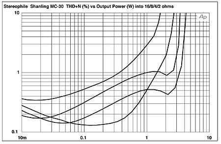 Fig.8 Shanling MC-30, left-channel distortion (%) vs 1kHz continuous output power into (from bottom to top at 100mW): 16, 4, 8, 2 ohms.
Because of the limited output power, I assessed how the THD+N percentage changed with frequency at 500mV rather than the usual 2.83V. The results are shown in fig.9: The blue traces show the performance of the left channel, which is what I used to generate fig.8. The amplifier's THD rises significantly only below 200Hz, due to the transformer core starting to saturate, and above the audioband, as well as into loads lower than 4 ohms. However, the right channel (red traces) behaves rather differently. The right channel's audioband THD+N percentage is slightly higher than the left's into 8 and 4 ohms, but now the lowest distortion is obtained into 2 ohms! The right channel's rise at low frequencies is similar to the left's, but there is a greater increase at ultrasonic frequencies.
Fig.8 Shanling MC-30, left-channel distortion (%) vs 1kHz continuous output power into (from bottom to top at 100mW): 16, 4, 8, 2 ohms.
Because of the limited output power, I assessed how the THD+N percentage changed with frequency at 500mV rather than the usual 2.83V. The results are shown in fig.9: The blue traces show the performance of the left channel, which is what I used to generate fig.8. The amplifier's THD rises significantly only below 200Hz, due to the transformer core starting to saturate, and above the audioband, as well as into loads lower than 4 ohms. However, the right channel (red traces) behaves rather differently. The right channel's audioband THD+N percentage is slightly higher than the left's into 8 and 4 ohms, but now the lowest distortion is obtained into 2 ohms! The right channel's rise at low frequencies is similar to the left's, but there is a greater increase at ultrasonic frequencies.
 Fig.9 Shanling MC-30, THD+N (%) vs frequency at 500mV into (from bottom to top at 1kHz): 16, 8, 4, 2 ohms (left channel blue, right channel red).
Working against the audibility of the distortion is the fact that it is almost pure second-harmonic in nature at midrange and high frequencies (fig.10). At low frequencies, the third harmonic makes an appearance, as does a regular series of higher harmonics (fig.11). Again the two channels differ slightly in how they behave, with the fourth harmonic higher in the right channel than the left but the second harmonic lower. This could be due merely to the inevitable differences between nominally identical tubes when used in a low-feedback, single-ended circuit. Despite its decreasing output-stage linearity above the audioband, the Shanling performed surprisingly well on the demanding high-frequency intermodulation test (fig.12). The 1kHz difference tone lay at a quite respectable –72dB (0.02%) in the left channel, though a less good –54dB (0.2%) in the right.
Fig.9 Shanling MC-30, THD+N (%) vs frequency at 500mV into (from bottom to top at 1kHz): 16, 8, 4, 2 ohms (left channel blue, right channel red).
Working against the audibility of the distortion is the fact that it is almost pure second-harmonic in nature at midrange and high frequencies (fig.10). At low frequencies, the third harmonic makes an appearance, as does a regular series of higher harmonics (fig.11). Again the two channels differ slightly in how they behave, with the fourth harmonic higher in the right channel than the left but the second harmonic lower. This could be due merely to the inevitable differences between nominally identical tubes when used in a low-feedback, single-ended circuit. Despite its decreasing output-stage linearity above the audioband, the Shanling performed surprisingly well on the demanding high-frequency intermodulation test (fig.12). The 1kHz difference tone lay at a quite respectable –72dB (0.02%) in the left channel, though a less good –54dB (0.2%) in the right.
 Fig.10 Shanling MC-30, 1kHz waveform at 1V into 4 ohms (top), 0.135% THD+N; distortion and noise waveform with fundamental notched out (bottom, not to scale).
 Fig.11 Shanling MC-30, spectrum of 1kHz sinewave, DC–1kHz, at 1V into 4 ohms (linear frequency scale; left channel blue, right channel red).
 Fig.12 Shanling MC-30, HF intermodulation spectrum, DC–24kHz, 19+20kHz at 1V peak into 4 ohms (linear frequency scale; left channel blue, right channel red).
The Shanling MC-30's CD-player section is not compromised at all by its inclusion in an affordable "Music Center." Its low level of background noise, excellent linearity, and superb error correction are better than those of some more expensive standalone players. The MC-30's output stage, of course, is compromised by the decision to use a single-ended tubed output stage. But it actually measures well for such a design, particularly into lower impedances, and I was impressed by the quality of the output transformers. Considering that the package costs a dollar less than $1000, looks stunning, and is well made to boot, this is pretty good performance overall.—John Atkinson
Fig.12 Shanling MC-30, HF intermodulation spectrum, DC–24kHz, 19+20kHz at 1V peak into 4 ohms (linear frequency scale; left channel blue, right channel red).
The Shanling MC-30's CD-player section is not compromised at all by its inclusion in an affordable "Music Center." Its low level of background noise, excellent linearity, and superb error correction are better than those of some more expensive standalone players. The MC-30's output stage, of course, is compromised by the decision to use a single-ended tubed output stage. But it actually measures well for such a design, particularly into lower impedances, and I was impressed by the quality of the output transformers. Considering that the package costs a dollar less than $1000, looks stunning, and is well made to boot, this is pretty good performance overall.—John Atkinson
Fig.1 Shanling MC-30, CD frequency response at –12dBFS into 100k ohms, measured at preamp output, with (bottom) and without (top) pre-emphasis (right channel dashed; 0.5dB/vertical div.).
Fig.2 Shanling MC-30, 1/3-octave spectrum with noise and spuriae of dithered 1kHz tone at –90dBFS with 16-bit data (right channel dashed).
Fig.3 Shanling MC-30, waveform of undithered 1kHz sinewave at –90.31dBFS, 16-bit data (left channel blue, right channel red).
Fig.4 Shanling MC-30, high-resolution jitter spectrum of analog output signal at preamp output, 11.025kHz at –6dBFS, sampled at 44.1kHz with LSB toggled at 229Hz, 16-bit CD data. Center frequency of trace, 11.025kHz; frequency range, ±3.5kHz (left channel blue, right channel red).
Turning to the MC-30's performance as a line preamplifier, feeding signals into the Aux input and again looking at the preamplifier output, the Shanling was again non-inverting, and its maximum gain was a sensibly modest 1.4dB. The input impedance was a reasonably high 26k ohms across the audioband, and the output impedance was a fairly high 1k ohm at middle and high frequencies, rising slightly to 1.3k ohms at 20Hz. The frequency response was flat up to the top of the audioband, and rolled off to reach –3dB at a very high 200kHz (not shown). Channel separation in the midrange was 110dB L–R but 90dB R–L.
Fig.5 Shanling MC-30, frequency response at 1V into: simulated loudspeaker load (red), 16 (cyan), 8 (blue), 4 (green), 2 (magenta) ohms (1dB/vertical div.).
The Shanling's small-signal frequency response into a resistive load was flat from 20Hz to 20kHz, but its out-of-band behavior varied with load impedance. As the load impedance increased from 2 ohms (fig.5, magenta) to 16 ohms (cyan), a small peak increasingly developed at 13Hz, and a larger one at about 160kHz. Conversely, as the load impedance dropped, another small peak, at 50kHz, increased in level. None of this behavior will be audible in itself, though it does reveal that the output transformer suffers from some mild ultrasonic instability. (This is very hard to avoid with an air-gapped design, which is essential for use with a single-ended output stage.) Though the MC-30's reproduction of a 1kHz squarewave is beautifully square with very short risetimes (fig.6), some overshoot and ringing are present, which can be seen in more detail with the 10kHz squarewave (fig.7).
Fig.6 Shanling MC-30, small-signal 1kHz squarewave into 8 ohms.
Fig.7 Shanling MC-30, small-signal 10kHz squarewave into 8 ohms.
Channel separation was a little compromised compared with the preamp section, with a typical midband figure of 69dB in both directions. Noise was low overall, however, the A-weighted signal/noise ratio (ref. 1W into 8 ohms, with the input shorted but the volume control set to "Max") measuring a good 81.4dB. This worsened to 63.2dB with a wideband, unweighted measurement, due to the presence of some fairly low-level 120Hz power-supply hum.
Specified as having a modest 3W maximum output (4.8dBW), the Shanling actually slightly exceeded this figure at clipping (1% THD) into 4 ohms, with 3.4W available (fig.8, right-hand trace). Relaxing the criterion to 3% THD allowed the amplifier to give just over 3W into 8 ohms, though considerably less power was available into 2 ohms (left-hand trace). The THD+noise never reaches a really low figure, but at levels of around 100mW and below it is acceptably low in level, particularly into 16 ohms. Peculiarly, the amplifier also appears to be more linear into 4 ohms than into 8.
Fig.8 Shanling MC-30, left-channel distortion (%) vs 1kHz continuous output power into (from bottom to top at 100mW): 16, 4, 8, 2 ohms.
Fig.9 Shanling MC-30, THD+N (%) vs frequency at 500mV into (from bottom to top at 1kHz): 16, 8, 4, 2 ohms (left channel blue, right channel red).
Working against the audibility of the distortion is the fact that it is almost pure second-harmonic in nature at midrange and high frequencies (fig.10). At low frequencies, the third harmonic makes an appearance, as does a regular series of higher harmonics (fig.11). Again the two channels differ slightly in how they behave, with the fourth harmonic higher in the right channel than the left but the second harmonic lower. This could be due merely to the inevitable differences between nominally identical tubes when used in a low-feedback, single-ended circuit. Despite its decreasing output-stage linearity above the audioband, the Shanling performed surprisingly well on the demanding high-frequency intermodulation test (fig.12). The 1kHz difference tone lay at a quite respectable –72dB (0.02%) in the left channel, though a less good –54dB (0.2%) in the right.
Fig.10 Shanling MC-30, 1kHz waveform at 1V into 4 ohms (top), 0.135% THD+N; distortion and noise waveform with fundamental notched out (bottom, not to scale).
Fig.11 Shanling MC-30, spectrum of 1kHz sinewave, DC–1kHz, at 1V into 4 ohms (linear frequency scale; left channel blue, right channel red).
Fig.12 Shanling MC-30, HF intermodulation spectrum, DC–24kHz, 19+20kHz at 1V peak into 4 ohms (linear frequency scale; left channel blue, right channel red).