Sidebar 3: Measurements
I used DRA Labs' MLSSA system and a calibrated DPA 4006 microphone to measure the Pioneer SP-BS22-LR's frequency response in the farfield, and an Earthworks QTC-40 for the nearfield responses. For logistical reasons, the sample I measured, serial no. LFNV0082030C, was from a different pair from the ones auditioned by Bob Reina.
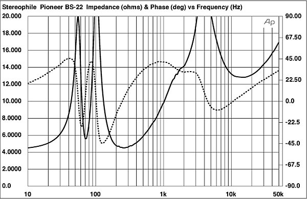
Pioneer specifies the 'BS22's voltage sensitivity as 85dB/2.83V/m. My B-weighted estimate was actually a little higher, at 86dB(B)/2.83V/m. Fig.1 shows how the Pioneer's impedance magnitude and electrical phase vary with frequency. The minimum impedance is 4.5 ohms at 250Hz, and there is a combination of 6 ohms and –33° at 160Hz, but neither of these affects the fact that the speaker is relatively easy to drive. The specified impedance of 6 ohms is a little on the conservative side, given that the SP-BS22-LR's impedance remains above 10 ohms for the entire treble region.
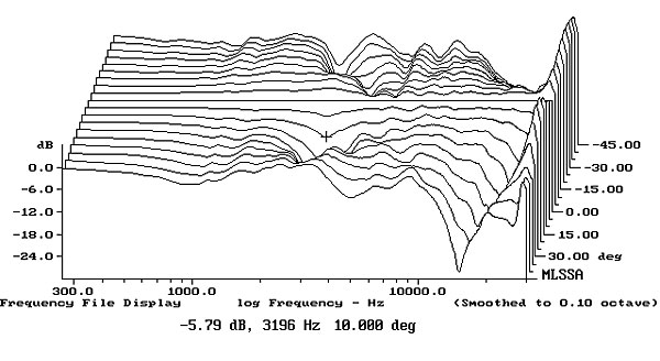
 Higher in frequency in fig.3, the Pioneer's farfield response, taken with its plastic-frame grille removed, slopes up a little from the lower midrange to the upper midrange, but with then a flat response through to the top octave where there is a slight excess of energy. This will tend to compensate to some extent for the speaker's dramatically restricted horizontal radiation pattern above 8.5kHz (fig.4), which is very similar to the older Pioneer's. Similarly, the slight flare in the off-axis behavior in fig.4 coincides with a slight lack of energy in the on-axis response, shown in fig.3. In the vertical plane (fig.5), a suckout in the crossover region develops more than 5° above and 10° below the tweeter axis. Using stands to bring the tweeters to the same height as the listener's ears will be critical with this speaker.
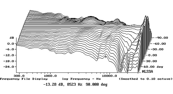
 In the time domain (fig.6), the tweeter's output leads that of the woofer, but its decay blends smoothly with the arrival of the woofer's output, implying optimal crossover design. Both drivers are connected in positive acoustic polarity. The SP-BS22-LR's cumulative spectral-decay or waterfall plot (fig.7) is impressively clean throughout the treble, though there is a small ridge of delayed energy at 1776Hz, this corresponding to the ripples seen in the decay of the woofer's step response.
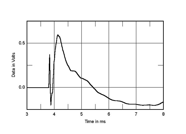
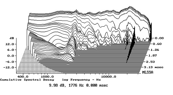
Fig.1 Pioneer SP-BS22-LR, electrical impedance (solid) and phase (dashed) (2 ohms/vertical div.).
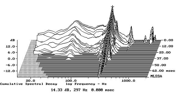
There are small wrinkles in the impedance traces just above 200 and 300Hz, as well as one around 1600Hz, which would imply the presence of enclosure resonances of some kind at these frequencies. However, using a plastic-tape accelerometer to investigate the cabinet's vibrational behavior with the speaker supported on upturned cones, which allows resonances to develop to their fullest, the strongest mode I could find was on the sidewalls, at 297Hz (fig.2). This mode was also present on the top panel, as well as others at 357Hz and 1kHz (not shown). I would have expected this mode to add some midrange congestion, and it's fair to note that BJR did comment on there being "a subtle bit of chestiness in the speaker's lower midrange."
Fig.2 Pioneer SP-BS22-LR, cumulative spectral-decay plot calculated from output of accelerometer fastened to center of side panel (MLS driving voltage to speaker, 7.55V; measurement bandwidth, 2kHz).
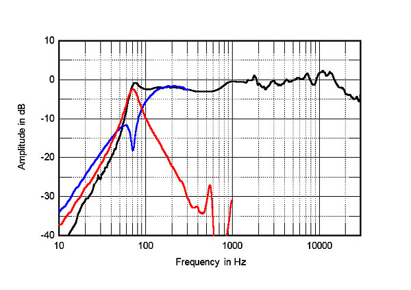
In the impedance-magnitude trace (fig.1, solid), the valley centered on 71Hz between the twin peaks in the bass suggests that this is the tuning frequency of the rear-firing port. This was confirmed by the fact that the minimum-motion notch in the woofer's nearfield output (fig.3, blue trace) occurs at the same frequency, which is about 11Hz higher than that of the SP-BS41-LR but lower than the tuning frequency of its predecessor, the SP-BS21-LR. The sharp peak at the tuning frequency in the port's output (red trace, plotted in the ratio of its diameter to the woofer's diameter) suggests a high-Q woofer alignment. This is probably a good idea, given that the driver's radiating diameter is just 3.5". There are a couple of resonant modes in the port's midrange output, but these are well suppressed. The complex sum of the nearfield woofer and port responses (fig.3, black trace below 300Hz) peaks a little at the port tuning frequency before rolling off rapidly, though the ultimate rolloff slope is a little slower than the usual 24dB/octave. There is only a hint of the usual upper-bass boost that results from the nearfield measurement technique.
Fig.3 Pioneer SP-BS22-LR, anechoic response on HF axis at 50", averaged across 30° horizontal window and corrected for microphone response, with nearfield responses of woofer (blue) and port (red) respectively plotted below 300 and 900Hz, and complex sum of nearfield responses plotted below 300Hz (black).
Fig.4 Pioneer SP-BS22-LR, lateral response family at 50", normalized to response on HF axis, from back to front: differences in response 90–5° off axis, reference response, differences in response 5–90° off axis.
Fig.5 Pioneer SP-BS22-LR, vertical response family at 50", normalized to response on HF axis, from back to front: differences in response 45–5° above axis, reference response, differences in response 5–45° below axis.
Fig.6 Pioneer SP-BS22-LR, step response on HF axis at 50" (5ms time window, 30kHz bandwidth).
Fig.7 Pioneer SP-BS22-LR, cumulative spectral-decay plot on HF axis at 50" (0.15ms risetime).
Considering it costs just a penny under $160/pair (and is often advertised for $130/pair), the Pioneer SP-BS22-LR shows little compromise in its measured performance, other than its necessarily limited low-frequency response and correspondingly underdamped woofer alignment. I was alarmed by that lively enclosure, but the radiating area of the affected panels is, of course, small, and this will also be influenced by the coupling material used on the stands' top plates. Measurements I did 20 years ago indicated that small pads of Blu-Tack were very good at damping cabinet resonances. (See "The Sound of Surprise.")—John Atkinson