Michael, who might be termed our typical audiophile (if anything in Santa Fe can be termed "typical"), may have found his digital processor, but he's still in a quandary about choosing the right power amp to drive his new loudspeakers. He has listened to a number of them over the past few months, and has been unable to find one which satisfies him in every way. I suspect he has a lot of company. The thorny problems of room acoustics and placement aside, loudspeakers are easier. Their signatures are pronounced and generate strong feelings one way or another; it's usually no problem to narrow down one's choices in this category.
But amplifiers? Even "experts" differ as to the degree and importance (or even the existence) of audible differences between them, though only a few would argue that they vary in sound as much as do loudspeakers. Still, no one here (and not many of our readers, I suspect) would contend that the only things that matter in an amplifier are to be found in the spec sheet. For most of us, the right amplifier in the right system can poke a significant hole in the curtain which continues to separate merely good reproduction from convincing recreation.
The amplifier under consideration here does just that. There's a school of thought which argues for the sonic superiority of lower-powered amplifiers—when used within their power limitations. A compelling case may be made for this. Freed from the problems which must be solved just to put out high power, the designer is able to concentrate more fully on sound quality. The entire amplifier is under less stress, and pressures pushing up costs are reduced. But would these advantages outweigh the sonic sacrifices that might result from modest power output? (footnote 1) I had hopes that perhaps this review would provide an answer.
Jeff Rowland Design Group Model 1: $3100
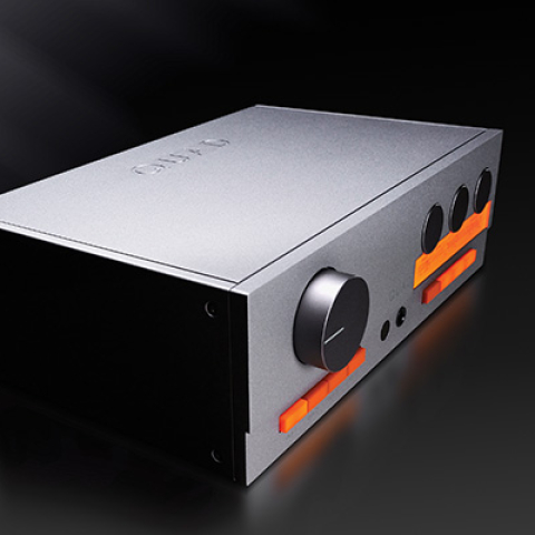
The Jeff Rowland Design Group, in the few years that they have been internationally visible in the audio high-end, have become solidly entrenched as one of the industry's heavyweights. But their Model 1 amplifier is almost petite, a significant departure from their flagship—the three-men-and-a-(husky)-boy-required-to-lift monoblock
Model 7. I couldn't help but think when I first laid eyes on it that this is the size an amplifier
ought to be. Not, perhaps, a practical objective, since increasing the power output of an amplifier extracts its own penalties in size and weight. But there's something to be said for an amplifier that one person can carry around.
The front panel of the Model 1 is devoid of what in Japanese styling parlance is known as "visual entertainment," save for the Rowland logo and the single, pushbutton on-off switch. This is not actually an on-off switch at all, but switches between standby mode, in which the low-level stages of the amplifier are powered-up, and full-on mode, which also powers the output stages. A true power switch is located on the rear panel of the amplifier, and is designed to be left on continuously (with the amplifier in standby when not in use). Also on the rear panel are all inputs (normal and inverting single-ended and balanced), DIP switches for selecting from the three available input impedances, a bridging switch which permits easy configuration of the Model 1 to a monoblock, and two pairs of output connectors per channel, making for easy bi-wire hookups. These connectors are heavy-duty, screw-type barrier strips. I did have an occasional problem in attaching loudspeaker cable having unusually broad spade-lugs to them, but these could usually be crimped slightly to fit.
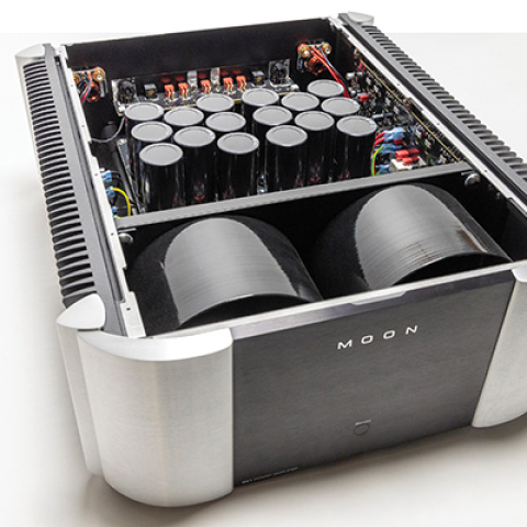
I can't fail to mention the outstanding fit and finish of the Model 1's exterior. I especially appreciated the rounded heatsinks flanking the amplifier on both sides. These were completely devoid of sharp edges, eliminating the risk of pinched fingers in moving the Rowland around, even without using the small, rack-mount–style handles attached to the rear panel. Inside, the Rowland appeared to be equally well built. The compact design means a rather fully packed interior (though not unreasonably so), with the single 600VA power transformer and two large, 32,000µF filter capacitors taking up much of the space. Much of the circuitry is encased in two sealed modules encapsulated in thermally conductive epoxy, mounted on two circuit boards, one on each side of the chassis. Switches mounted on the underside of these modules allow the gain to be reset (from the factory setting of 26dB) to 20, 29.5, or 32dB. Rowland recommends that any such adjustment be made by a Rowland dealer (incorrect reinsertion of the modules is not covered by warranty).
Technical details
The design concepts and circuit topologies of the Model 1 are similar to those of Rowland's higher-powered amplifiers. The smaller physical size and reduced power-supply capacity—reflected in the more modest power output—are the only significant differences. Even so, the Model 1 was designed from the bottom up to be able to perform in the bridged mode as a 250W mono amplifier, with its power supply and output stages designed to avoid sonic degradation when used as a monoblock (footnote 2). The main power supply feeds the output stage, with its 12 150W bipolar transistors per channel. These transistors are mounted on a 13mm (over 0.5") thick, solid aluminum plate on the inner surface of the heatsinks. An additional secondary winding on the main transformer, suitably filtered, separately drives a "housekeeping" power supply which operates the turn-on logic control and protection circuitry. A further set of secondary windings supplies current to a high-voltage DC supply dedicated to the front-end circuitry.
The latter consists of two stages. The first, located near the rear panel inputs, Rowland refers to as a "differential transconductance" stage. It derives a single-phase proportional
current from either the amplifier's single-ended or balanced input. Rowland calls the second stage a transimpedance mode amplifier, a voltage gain stage which responds directly to this current output from the first stage. Rowland claims that this circuit implementation provides desirable improvements in dynamic characteristics and high-frequency performance compared with more traditional topologies.
The Model 1 is direct-coupled from input to output, using a DC servo to compensate for long-term drift. Local feedback is used, but the amplifier does not employ overall or global feedback. Protection circuitry shuts down the amplifier in the event of damaging failure modes, including DC on the outputs and overheating.
Just before serious auditioning of our Model 1 was to begin, we were notified of a design change to the amplifier, including modifications to the input stages (specifically to the "transimpedance" circuitry within the encapsulated modules, discussed above), a change in the output stage bias current, and minor modifications to the power supply. We returned our Model 1 for a replacement. I had been very favorably impressed by the initial sample, but since the old and new versions were not available to us simultaneously for side-by-side comparisons, all of my sonic observations here relate to the latest sample, which is typical of Model 1s manufactured after November 1990.
I encountered two minor operational problems with our samples of the Model 1. First, blown fuses. This occurred twice, once in normal operation and a second time when I encountered a static-electricity problem with the Consonance preamp (subsequent to the March 1991 review of that unit). On the first occasion, a single power-supply fuse blew for no apparent reason. On the second, all four power-supply fuses went south and had to be replaced (the fuses are mounted internally). No surges or pulses were audible through the loudspeakers in either case; replacement of the fuses restored full, normal operation, and there was no subsequent recurrence of either event.
The second problem was that of "frozen" screws on the output barrier strips. One of the screws on the first version and two on its replacement jammed to where they could not be tightened or loosened without the use of excessive force. Fortunately, redundant terminal strips for bi-wiring prevented the amplifier from going out of action. I recommend care in making connections to these terminals, though I do not feel that I stressed them in any unusual fashion.
Matters of Balance, Impedance Matching, and other Related Stuff
Rowland now provides balanced outputs on all of their preamplifiers and balanced inputs on all of their power amplifiers, and is a strong proponent of the practice (as are many other manufacturers). A paper discussing the concept and the reasons for Rowland's endorsement of it is available from that manufacturer, and is bound into all of their owners' manuals—they refer to it as differential-mode technology.
As I mentioned in my recent review of it (Vol.14 No.3), I found the Rowland Consonance preamp's performance to be on an equivalent level in my system with either balanced or unbalanced connection to the power amp. The advantages of balanced operation will very much depend on the system and its environment—its main advantage is, after all, improved rejection of outside noise. I would also expect it to be of more importance in low-level signals—phono to preamp especially—which the preamps on-hand did not permit. It would be, in my judgment, unwarranted to assume that balanced lines will improve the sound in
all systems and
all situations, and I have not yet convinced myself that, in the preamp-to-power-amp link, balanced operation provides a real improvement in
my system. Nevertheless, like chicken soup, there is no reason
not to use balanced interconnects, if and where the system provides for it. All of my listening observations of both amplifiers in this review were therefore made with balanced lines between the preamp and the power amp.
The Rowland Model 1 also provides for adjustable input impedances of 600 ohms, 20k ohms, and 100k ohms. Rowland makes a case for 600 ohms input impedance being the proper load when used with a source capable of driving it (their own preamps are designed to do so). They believe that this improves the interface between line-level components by treating the cable as a transmission line and maximizing power transfer. There is, of course, strong justification for this during the transmission of, for instance, microwave energy—when you're feeding power from a radio transmitter to an antenna, you don't want to lose any more of it than you have to. But in line-level audio signal transfer, you're relaying a
voltage, not power, from one line-level device to another, a voltage which will act as a control signal to, in effect, modulate the output voltage of the second device. The current between the two devices, except in certain special circumstances (loudspeakers being a major example), is of no importance and in fact may be a detriment if the first device is unable to provide the current.
That's why line-level devices in audio nearly always feed into a high impedance; the resultant current flow between the two devices is thus kept negligible. (A different set of considerations results when the source or the load is passive, not active.) We are not attempting to transmit power until we need to drive a loudspeaker. If both the source and the load devices are designed to be compatible with such a loading arrangement, I see no reason why it can't be used, but neither do I see the theoretical advantage. But then, I've always been dubious about attempts to apply transmission-line theory—which is designed for RF transmission—to audio frequency design (footnote 3).
Still, there's much that we don't yet understand. I did experiment with using the 600 ohm input impedance of the Model 1, comparing it to the 20k ohm setting. My general preference was for the 20k. The main difference I noted was in the high frequencies. In the 600 ohm position, the sound was a trace brighter and more detailed, but the highs were also somewhat grainier. I did not consider the net result to be a plus. If you should invest in a Model 1 and have a preamp which will work properly into the 600 ohm load, it will cost nothing for you to try it and come to your own conclusion. But I used the 20k setting for the bulk of my listening not only because I preferred it, but because my results will be more generally applicable to users who might use other than 600 ohm–load compatible preamps.
I have to remark here on the importance of proper level matching when comparing balanced to unbalanced operation (the former provides a theoretical 6dB increase in gain) or various input impedances (the 600 ohm setting results in an equivalent loss when compared with the 20k ohm). On a number of instances during my auditions, I found that one setting or another sounded a trace more dynamic or bright, only to find that it was playing
less than 0.5dB louder. And we are not talking direct A/B comparisons here, but comparisons with a brief time gap required to reconfigure the system and reset the level. The significance of this for casually level-matched listening tests cannot be ignored.
Sound
The Rowland Model 1 may just be too self-effacing for its own good. It refuses to jump out and grab the listener by the throat. It grows on you slowly. When
Stereophile's equipment reviewers gathered in the
Stereophile listening room last summer to hear the
Apogee Stage speakers, the original version of the Rowland was on hand to do the honors. Peter Mitchell reported on this event in his column in Vol.13 No.11 (November 1990). To make a long story short, he (and many of those assembled) felt the sound to be too dark, and the system restricted in ultimate output level with the Rowland 1 in the chain.
Footnote 1: The term "modest," when applied to power output, is admittedly vague. I would specify it as, very broadly, output between 40 and 100W (into 8 ohms). At one time, 60W was considered to be high power. No longer.
Footnote 2: Time and space did not permit evaluation of the Model 1 in the bridged mode for this review, but as two of the amplifiers remain on hand, a Follow-Up assessing its use in this mode will be published at a later date.
Footnote 3: Some have held that forcing line-level interconnects to carry a relatively sizeable current will minimize diodic effects in the metal-metal contacts in the connectors.—
John Atkinson