
Sidebar 3: Measurements
I performed all my measurements using the CD1 input. I didn't measure the Audio Valve Eclipse from its XLR jacks, however. As explained in the manual, these are not true balanced outputs; instead, they are unbalanced, paralleling the output on the RCA jacks on pin 2, with pin 3 connected to ground. The preamplifier's maximum voltage gain from the CD1 input was a modest 7.15dB, with the unity-gain setting of the volume control at 4:00. The gains from the other inputs ranged from 5.15dB, CD2 to 15.9dB, tuner and tape. It looks as if the different input sensitivities are set by resistive divider ladders on the input jacks. I must say that this is suboptimal engineering, as it compromises the S/N ratio by the amount of gain reduction. The Eclipse was non-inverting; ie, it preserved absolute polarity.
The input impedance was 20k ohms across the audioband; the output impedance was 320 ohms at midrange and high frequencies, but rose to a very high 3090 ohms at 20Hz. As a result, the Eclipse's frequency response into low impedances will be prematurely rolled off in the bass (fig.1, bottom pair of traces below 1kHz). This preamplifier needs to be used with a power amplifier having an input impedance of at least 30k ohms in order for it to deliver a full measure of low frequencies. At the other end of the spectrum, the Eclipse didn't start rolling off until frequencies above 20kHz, reaching –3dB at 115kHz. This was with the volume control set to its maximum; the bandwidth shrank at lower settings, to –3dB at 75kHz at the unity gain setting, this resulting in the output being down 0.25dB at 20kHz.
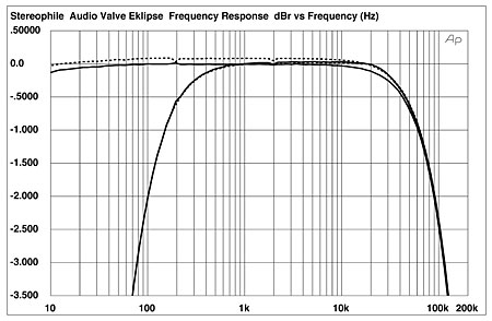 Fig.1 Audio Valve Eclipse, frequency response at 1V into 100k ohms (top below 1kHz) and 600 ohms (bottom below 1kHz) with volume control set to maximum (0.5dB/vertical div., right channel dashed).
Channel separation was good, at >80dB in both directions below 1.7kHz (not shown), though it did decrease at low frequencies, suggesting a higher-than-normal power-supply impedance in the bass. Noise levels were slightly affected by some low-level 120Hz power-supply hum, which I couldn't completely eliminate by experimenting with grounding between the preamp and my Audio Precision test system. The unweighted, wideband signal/noise ratio (ref. 1V output, with the volume control at its maximum setting) was 76.8dB from the CD1 input, this improving to 87.5dB when A-weighted. Without the input attenuator, I would expect these figures to be around 9dB better.
The Eclipse could deliver very high output voltages with moderately low distortion. Fig.2 shows how the THD+noise percentage changes with output level into loads ranging from 1k ohm to 100k ohms. The downward slope of the traces below 1V or so in this graph results from the measurement being dominated by noise. The actual THD starts to rise out of the noise when the traces "bottom"; the fact that this occurs between 1V and 2V into the higher impedances—the highest voltage the preamp will be asked to deliver into a typical power amplifier—suggests that the Eclipse's gain architecture has been sensibly arranged. The preamp is obviously not comfortable driving the lowest impedance (top trace), but peculiarly, the Eclipse is most linear into 10k ohms (bottom) rather than the usual 100k ohms (middle).
Fig.1 Audio Valve Eclipse, frequency response at 1V into 100k ohms (top below 1kHz) and 600 ohms (bottom below 1kHz) with volume control set to maximum (0.5dB/vertical div., right channel dashed).
Channel separation was good, at >80dB in both directions below 1.7kHz (not shown), though it did decrease at low frequencies, suggesting a higher-than-normal power-supply impedance in the bass. Noise levels were slightly affected by some low-level 120Hz power-supply hum, which I couldn't completely eliminate by experimenting with grounding between the preamp and my Audio Precision test system. The unweighted, wideband signal/noise ratio (ref. 1V output, with the volume control at its maximum setting) was 76.8dB from the CD1 input, this improving to 87.5dB when A-weighted. Without the input attenuator, I would expect these figures to be around 9dB better.
The Eclipse could deliver very high output voltages with moderately low distortion. Fig.2 shows how the THD+noise percentage changes with output level into loads ranging from 1k ohm to 100k ohms. The downward slope of the traces below 1V or so in this graph results from the measurement being dominated by noise. The actual THD starts to rise out of the noise when the traces "bottom"; the fact that this occurs between 1V and 2V into the higher impedances—the highest voltage the preamp will be asked to deliver into a typical power amplifier—suggests that the Eclipse's gain architecture has been sensibly arranged. The preamp is obviously not comfortable driving the lowest impedance (top trace), but peculiarly, the Eclipse is most linear into 10k ohms (bottom) rather than the usual 100k ohms (middle).
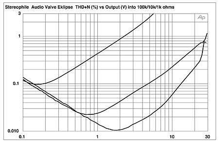 Fig.2 Audio Valve Eclipse, distortion (%) vs 1kHz output level into (from bottom to top at 2V): 10k, 100k, 1k ohms.
Plotting the THD+N percentage at an output level of 1V into a range of load impedances gave the graph shown in fig.3. Again, the preamplifier is most linear into 10k ohms (bottom trace), but also again, the Eclipse is uncomfortable driving a load as low as 1k ohm (top trace). However, the THD+N into 5k ohms (second trace from top) is not much worse than that into 100k ohms (third trace from top), suggesting that the preamp will be well behaved with real-world power amplifiers.
Fig.2 Audio Valve Eclipse, distortion (%) vs 1kHz output level into (from bottom to top at 2V): 10k, 100k, 1k ohms.
Plotting the THD+N percentage at an output level of 1V into a range of load impedances gave the graph shown in fig.3. Again, the preamplifier is most linear into 10k ohms (bottom trace), but also again, the Eclipse is uncomfortable driving a load as low as 1k ohm (top trace). However, the THD+N into 5k ohms (second trace from top) is not much worse than that into 100k ohms (third trace from top), suggesting that the preamp will be well behaved with real-world power amplifiers.
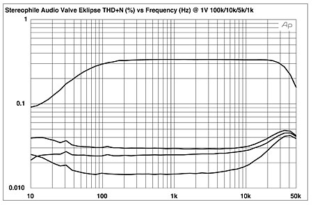 Fig.3 Audio Valve Eclipse, THD+N (%) vs frequency at 1V into (from bottom to top): 10k, 100k, 5k, 1k ohms.
As is usually the case with single-ended tube preamplifiers, the distortion spectrum consists predominantly of the subjectively benign second harmonic (fig.4), at levels of –68dB (left) and –70dB (right). However, the right channel has more third, fourth, and fifth harmonic evident (red trace), although still at a low level in absolute terms. Intermodulation distortion was also relatively low (fig.5), with the difference component resulting from an equal mix of 19 and 20kHz tones lying at –73dB (0.023%). This was into a fairly low impedance; into 100k ohms, the difference component rose to –62dB (0.076%), though this is still low.
Fig.3 Audio Valve Eclipse, THD+N (%) vs frequency at 1V into (from bottom to top): 10k, 100k, 5k, 1k ohms.
As is usually the case with single-ended tube preamplifiers, the distortion spectrum consists predominantly of the subjectively benign second harmonic (fig.4), at levels of –68dB (left) and –70dB (right). However, the right channel has more third, fourth, and fifth harmonic evident (red trace), although still at a low level in absolute terms. Intermodulation distortion was also relatively low (fig.5), with the difference component resulting from an equal mix of 19 and 20kHz tones lying at –73dB (0.023%). This was into a fairly low impedance; into 100k ohms, the difference component rose to –62dB (0.076%), though this is still low.
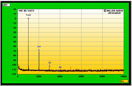 Fig.4 Audio Valve Eclipse, spectrum of 1kHz sinewave, DC–10kHz, at 1V into 8k ohms (linear frequency scale).
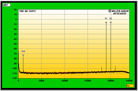 Fig.5 Audio Valve Eclipse, HF intermodulation spectrum, DC–24kHz, 19+20kHz at 1V peak into 8k ohms (linear frequency scale).
Provided it is used with power amplifiers having an input impedance of at least 30k ohms, the Audio Valve Eclipse measures well for a tube design, with its performance optimized for real-world conditions. But I am not impressed by the way in which the different input sensitivities has been implemented.—John Atkinson
Fig.5 Audio Valve Eclipse, HF intermodulation spectrum, DC–24kHz, 19+20kHz at 1V peak into 8k ohms (linear frequency scale).
Provided it is used with power amplifiers having an input impedance of at least 30k ohms, the Audio Valve Eclipse measures well for a tube design, with its performance optimized for real-world conditions. But I am not impressed by the way in which the different input sensitivities has been implemented.—John Atkinson
Fig.1 Audio Valve Eclipse, frequency response at 1V into 100k ohms (top below 1kHz) and 600 ohms (bottom below 1kHz) with volume control set to maximum (0.5dB/vertical div., right channel dashed).
Fig.2 Audio Valve Eclipse, distortion (%) vs 1kHz output level into (from bottom to top at 2V): 10k, 100k, 1k ohms.
Fig.3 Audio Valve Eclipse, THD+N (%) vs frequency at 1V into (from bottom to top): 10k, 100k, 5k, 1k ohms.
As is usually the case with single-ended tube preamplifiers, the distortion spectrum consists predominantly of the subjectively benign second harmonic (fig.4), at levels of –68dB (left) and –70dB (right). However, the right channel has more third, fourth, and fifth harmonic evident (red trace), although still at a low level in absolute terms. Intermodulation distortion was also relatively low (fig.5), with the difference component resulting from an equal mix of 19 and 20kHz tones lying at –73dB (0.023%). This was into a fairly low impedance; into 100k ohms, the difference component rose to –62dB (0.076%), though this is still low.
Fig.4 Audio Valve Eclipse, spectrum of 1kHz sinewave, DC–10kHz, at 1V into 8k ohms (linear frequency scale).
Fig.5 Audio Valve Eclipse, HF intermodulation spectrum, DC–24kHz, 19+20kHz at 1V peak into 8k ohms (linear frequency scale).
Provided it is used with power amplifiers having an input impedance of at least 30k ohms, the Audio Valve Eclipse measures well for a tube design, with its performance optimized for real-world conditions. But I am not impressed by the way in which the different input sensitivities has been implemented.—John Atkinson


