As mentioned by two readers in this month's "Letters," amplifiers are used to drive loudspeakers but are almost exclusively measured into resistive loads. The reasons for this are twofold: 1) real loudspeakers both produce neighbor-annoying sound levels and tend to break when driven with typical amplifier test signals; and 2) the question as to which "standard" loudspeaker should be used is impossible to answer---at least the conventional resistive loads are consistent and repeatable. However, the general point that an amplifier should be measured into a load similar to that of a real loudspeaker is a valid one. Loudspeakers can be much more demanding than resistive loads, as evidenced by Eric Benjamin's 1993 AES paper, "Audio Power Amplifiers for Loudspeaker Loads." We had been thinking about how to implement this for some time, when, as a result of a chance conversation, Ken Kantor of NHT and International Jensen sent us a speaker simulator he had been using. Its circuit diagram is shown in fig.1. Combinations of resistors, inductors, and capacitors produce a load with an impedance magnitude and phase plot (fig.2) intended to represent a typical two-way, sealed-box, 8 ohm loudspeaker. (The small-value resistors shown are the measured series resistances of the coils.) The impedance peak in the bass is the equivalent of the woofer's enclosure resonance; the peak in the low treble is identical to that produced by a crossover filter. The phase angles are also typical; note that the worst-case phase never coincides with the lowest magnitude.
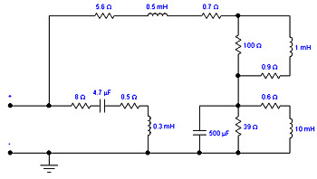 Fig.1 Circuit of Ken Kantor loudspeaker simulator, intended to represent a two-way, sealed-box minimonitor with a nominal impedance of 8 ohms.
 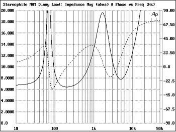 Fig.2 Kantor speaker simulator, electrical impedance (solid) and phase (dashed) (2 ohms/vertical div.).
Fig.1 Circuit of Ken Kantor loudspeaker simulator, intended to represent a two-way, sealed-box minimonitor with a nominal impedance of 8 ohms. Fig.2 Kantor speaker simulator, electrical impedance (solid) and phase (dashed) (2 ohms/vertical div.).