If you missed Part 1 of this article (Stereophile, January 2005), or it has faded in your memory, here's a résumé. (Readers who recall Part 1 with crystalline clarity, please skip to paragraph four.) The accurate measuring of loudspeakers requires that the measurements be taken in a reflection-free environment. Traditionally, this has meant that the speaker be placed atop a tall pole outdoors or in an anechoic chamber. Both of these options are hedged around with unwelcome implications of cost and practicality. To overcome these and allow quasi-anechoic measurements to be performed in normal, reverberant rooms, time-windowed measurement methods were developed that allow the user to analyze only that portion of the speaker's impulse response that arrives at the microphone ahead of the first room reflection. MLSSA from DRA Labs is the best-known measurement system to work on this principle, and both John Atkinson and I use it in the course of preparing our loudspeaker reviews.
 The downside of time-windowed measurement is that there is a concomitant restriction in frequency resolution. For example, if the maximum time window that can be achieved, from the beginning of the speaker's response to the arrival of the first reflection, is 6 milliseconds (6ms, or 0.006s—a typical figure in a domestic room), then the frequency resolution of the resulting measurement will be 1/0.006 = 167Hz. This makes accurate measurements at bass and lower-midrange frequencies impossible to achieve without resorting to subterfuge. A trick called nearfield measurement—in which the microphone is placed close against each of the speaker's bass radiators (diaphragms and ports)—allows the frequency response to be determined down to the lowest audio frequencies. But nearfield measurement reveals nothing about the speaker's cabinet resonances, the severest of which typically fall below 700Hz or so and cannot be well resolved using farfield measurement with a short time window. As these resonances are known to be a prime determinant of a speaker's sound quality, the inability to identify them in the course of speaker reviewing is a serious shortcoming.
To widen the time window and so improve the frequency resolution, the first obvious step is to use as large a room as possible in which to conduct the measuring. Conventionally, this would incur the practical problem of how to raise the speaker high enough off the floor to ensure the maximum delay before the arrival of the first room reflection. If the room's ceiling height is, say, 9 meters (30'), and this is the smallest room dimension, then to achieve the maximum delay the speaker will have to be lifted 4.5m (15') above the floor. But we can sidestep this onerous requirement, and potentially widen the time window still further, by borrowing a technique more usually deployed outdoors. Called ground-plane measurement, this places both the speaker and the microphone on the floor and achieves good low-frequency results quickly and easily. Moreover, as I showed in Part 1, the ground-plane concept can be extended to two or three planes, where the measurement microphone is placed at the junction of wall and floor or in a room corner. Depending on the dimensions of the room, this potentially allows the time window to be dilated even further.
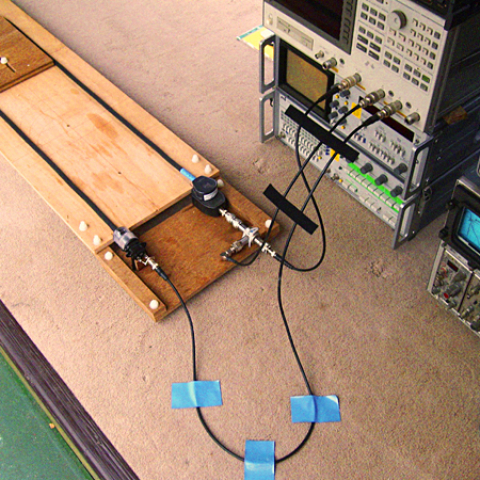
When I signed off on Part 1, this use of multiple planes was just a thought experiment—but I had in mind to try it for real in my local community hall. That plan was scuppered when it emerged that the hall's side walls were not plaster on brick, as I had thought, but dry-lined (ie, the inner walls are surfaced in skimmed plasterboard, spaced from the brick on wood battens). As the multiplane technique requires that all surfaces be nonresonant and fully reflective, this clearly wouldn't do, so I cast my net farther. Just four miles down the road I found a sports hall in the local secondary school that not only has hard, reflective walls (unfinished concrete blocks) but is even larger than my local hall: 33m (108') long by 18m (59') wide, although still with a ceiling height of around 9m (30'). So it was to this hall that I decamped one Saturday afternoon for a couple of hours, armed with my measurement gear and a B&W loudspeaker, the CDM1 NT, in the role of guinea pig.
What I did there was perform four equivalent measurements in the one- and two-plane arrangements, the primary task being to verify the latter by establishing that it would give results equivalent to those of the single-plane case. Before revealing the results, I should explain that there is a twist to the two-plane procedure that wasn't revealed in Part 1. What was shown there was a setup in which the speaker faces the sidewall, an arrangement that invites the problem illustrated in fig.1: reflections reaching the microphone after multiple bounces between the speaker (or speaker/stand) and wall. These short-delay reflections would undo the attempt to expand the measurement time window, but they can be easily countered by modifying the setup as shown in fig.2, which views the speaker and wall in plan view (ie, as viewed from above). Angling the speaker at 45º to the wall avoids parallel surfaces and substantially removes the reflection problem. Note that this arrangement is very like that which would pertain in the case of three-plane corner measurement; if it works here, it can be expected to work there too.
The downside of time-windowed measurement is that there is a concomitant restriction in frequency resolution. For example, if the maximum time window that can be achieved, from the beginning of the speaker's response to the arrival of the first reflection, is 6 milliseconds (6ms, or 0.006s—a typical figure in a domestic room), then the frequency resolution of the resulting measurement will be 1/0.006 = 167Hz. This makes accurate measurements at bass and lower-midrange frequencies impossible to achieve without resorting to subterfuge. A trick called nearfield measurement—in which the microphone is placed close against each of the speaker's bass radiators (diaphragms and ports)—allows the frequency response to be determined down to the lowest audio frequencies. But nearfield measurement reveals nothing about the speaker's cabinet resonances, the severest of which typically fall below 700Hz or so and cannot be well resolved using farfield measurement with a short time window. As these resonances are known to be a prime determinant of a speaker's sound quality, the inability to identify them in the course of speaker reviewing is a serious shortcoming.
To widen the time window and so improve the frequency resolution, the first obvious step is to use as large a room as possible in which to conduct the measuring. Conventionally, this would incur the practical problem of how to raise the speaker high enough off the floor to ensure the maximum delay before the arrival of the first room reflection. If the room's ceiling height is, say, 9 meters (30'), and this is the smallest room dimension, then to achieve the maximum delay the speaker will have to be lifted 4.5m (15') above the floor. But we can sidestep this onerous requirement, and potentially widen the time window still further, by borrowing a technique more usually deployed outdoors. Called ground-plane measurement, this places both the speaker and the microphone on the floor and achieves good low-frequency results quickly and easily. Moreover, as I showed in Part 1, the ground-plane concept can be extended to two or three planes, where the measurement microphone is placed at the junction of wall and floor or in a room corner. Depending on the dimensions of the room, this potentially allows the time window to be dilated even further.
When I signed off on Part 1, this use of multiple planes was just a thought experiment—but I had in mind to try it for real in my local community hall. That plan was scuppered when it emerged that the hall's side walls were not plaster on brick, as I had thought, but dry-lined (ie, the inner walls are surfaced in skimmed plasterboard, spaced from the brick on wood battens). As the multiplane technique requires that all surfaces be nonresonant and fully reflective, this clearly wouldn't do, so I cast my net farther. Just four miles down the road I found a sports hall in the local secondary school that not only has hard, reflective walls (unfinished concrete blocks) but is even larger than my local hall: 33m (108') long by 18m (59') wide, although still with a ceiling height of around 9m (30'). So it was to this hall that I decamped one Saturday afternoon for a couple of hours, armed with my measurement gear and a B&W loudspeaker, the CDM1 NT, in the role of guinea pig.
What I did there was perform four equivalent measurements in the one- and two-plane arrangements, the primary task being to verify the latter by establishing that it would give results equivalent to those of the single-plane case. Before revealing the results, I should explain that there is a twist to the two-plane procedure that wasn't revealed in Part 1. What was shown there was a setup in which the speaker faces the sidewall, an arrangement that invites the problem illustrated in fig.1: reflections reaching the microphone after multiple bounces between the speaker (or speaker/stand) and wall. These short-delay reflections would undo the attempt to expand the measurement time window, but they can be easily countered by modifying the setup as shown in fig.2, which views the speaker and wall in plan view (ie, as viewed from above). Angling the speaker at 45º to the wall avoids parallel surfaces and substantially removes the reflection problem. Note that this arrangement is very like that which would pertain in the case of three-plane corner measurement; if it works here, it can be expected to work there too.
 Fig.1 Multiple reflections between speaker/stand and wall can disrupt a two-plane measurement . . .
 Fig.2 . . . but this can be largely avoided by angling the speaker at 45º to the wall.
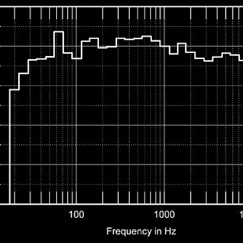
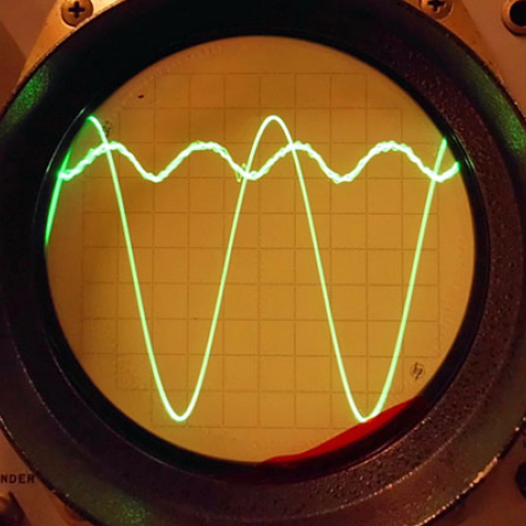
And work it does. Fig.3 superimposes the low-frequency frequency responses measured using the one- and two-plane techniques—they are effectively the same. So, too, are the cumulative decay spectra shown in figs.4a and 4b. There is a little more "clutter" in the two-plane plot at higher frequencies, probably due to some low-level reflections caused by various pieces of apparatus attached to the sports hall's sidewall, but in their major features the plots are substantially alike (and could probably be made more so by refining the time windowing of the two-plane measurement). These results confirm that, in appropriate rooms, the two- or even three-plane setups can indeed be used to open out the available time window, potentially by a significant amount. Ironically, this approach didn't benefit my work in the sports hall, but others in the audio industry will, I hope, find it useful. It is, at the very least, a trick worth having up your sleeve.
Fig.2 . . . but this can be largely avoided by angling the speaker at 45º to the wall.
And work it does. Fig.3 superimposes the low-frequency frequency responses measured using the one- and two-plane techniques—they are effectively the same. So, too, are the cumulative decay spectra shown in figs.4a and 4b. There is a little more "clutter" in the two-plane plot at higher frequencies, probably due to some low-level reflections caused by various pieces of apparatus attached to the sports hall's sidewall, but in their major features the plots are substantially alike (and could probably be made more so by refining the time windowing of the two-plane measurement). These results confirm that, in appropriate rooms, the two- or even three-plane setups can indeed be used to open out the available time window, potentially by a significant amount. Ironically, this approach didn't benefit my work in the sports hall, but others in the audio industry will, I hope, find it useful. It is, at the very least, a trick worth having up your sleeve.
 Fig.3 Comparison of frequency responses obtained using the one-plane (red trace) and two-plane (blue) setups. The disparities at higher frequencies are probably due to reflections from wall-mounted objects in the sports hall where these measurements were made.

 Fig.4 Comparison of cumulative decay spectra obtained using the one-plane (a, top) and two-plane (b) setups. Again, the small disparities are probably due to reflections.
The downside of time-windowed measurement is that there is a concomitant restriction in frequency resolution. For example, if the maximum time window that can be achieved, from the beginning of the speaker's response to the arrival of the first reflection, is 6 milliseconds (6ms, or 0.006s—a typical figure in a domestic room), then the frequency resolution of the resulting measurement will be 1/0.006 = 167Hz. This makes accurate measurements at bass and lower-midrange frequencies impossible to achieve without resorting to subterfuge. A trick called nearfield measurement—in which the microphone is placed close against each of the speaker's bass radiators (diaphragms and ports)—allows the frequency response to be determined down to the lowest audio frequencies. But nearfield measurement reveals nothing about the speaker's cabinet resonances, the severest of which typically fall below 700Hz or so and cannot be well resolved using farfield measurement with a short time window. As these resonances are known to be a prime determinant of a speaker's sound quality, the inability to identify them in the course of speaker reviewing is a serious shortcoming.
To widen the time window and so improve the frequency resolution, the first obvious step is to use as large a room as possible in which to conduct the measuring. Conventionally, this would incur the practical problem of how to raise the speaker high enough off the floor to ensure the maximum delay before the arrival of the first room reflection. If the room's ceiling height is, say, 9 meters (30'), and this is the smallest room dimension, then to achieve the maximum delay the speaker will have to be lifted 4.5m (15') above the floor. But we can sidestep this onerous requirement, and potentially widen the time window still further, by borrowing a technique more usually deployed outdoors. Called ground-plane measurement, this places both the speaker and the microphone on the floor and achieves good low-frequency results quickly and easily. Moreover, as I showed in Part 1, the ground-plane concept can be extended to two or three planes, where the measurement microphone is placed at the junction of wall and floor or in a room corner. Depending on the dimensions of the room, this potentially allows the time window to be dilated even further.
Fig.1 Multiple reflections between speaker/stand and wall can disrupt a two-plane measurement . . .
Fig.2 . . . but this can be largely avoided by angling the speaker at 45º to the wall.
And work it does. Fig.3 superimposes the low-frequency frequency responses measured using the one- and two-plane techniques—they are effectively the same. So, too, are the cumulative decay spectra shown in figs.4a and 4b. There is a little more "clutter" in the two-plane plot at higher frequencies, probably due to some low-level reflections caused by various pieces of apparatus attached to the sports hall's sidewall, but in their major features the plots are substantially alike (and could probably be made more so by refining the time windowing of the two-plane measurement). These results confirm that, in appropriate rooms, the two- or even three-plane setups can indeed be used to open out the available time window, potentially by a significant amount. Ironically, this approach didn't benefit my work in the sports hall, but others in the audio industry will, I hope, find it useful. It is, at the very least, a trick worth having up your sleeve.
Fig.3 Comparison of frequency responses obtained using the one-plane (red trace) and two-plane (blue) setups. The disparities at higher frequencies are probably due to reflections from wall-mounted objects in the sports hall where these measurements were made.
Fig.4 Comparison of cumulative decay spectra obtained using the one-plane (a, top) and two-plane (b) setups. Again, the small disparities are probably due to reflections.