| Columns Retired Columns & Blogs |
The DIY Chronicles, Part Three
Editor's Note: This is Part Three of a six-part series from reader Hervé Delétraz of Switzerland, who is chronicling the development of his DIY (do-it-yourself) audio amplifier. Part One is here, and Part Two is here.
After exploring the different amplifier topologies presented in the last article, I can now better explain what my design goals were—apart, of course, from building the best amp in the world! Your own kids are always the best, aren't they?
The goals:
• All bipolar, unbalanced, symmetrical topology.
• No compensation (no thermal or electrical) circuit.
• No switches, fuses, or relays in the signal path (including the power supplies).
• Highest possible input impedance.
• Lowest possible output impedance.
• Full DC coupling.
• Wide bandwidth.
• Lowest possible negative feedback.
• The fewest components I could use.
Some might say that many of these are contradictory goals. They'd be almost right. I wanted to use a bipolar topology because the input capacitance is negligible, so the frequency response would be much less dependent on the input cable length and preamplifier output impedance. When properly driven, power bipolars are as quick as MOSFETs.
I would avoid any thermal/electrical compensation because it involves additional devices that regulate the bias current vs. the heatsink temperature. This circuit is normally unavoidable, to prevent having a thermal runaway, but I wanted to omit it. I also wanted no fuses, switches, or relays for the obvious reason: sound purity. But I might keep protection in the design for a possible future commercial version of the amp, so the protection circuit would have to be special.
I wanted full DC coupling in order to reproduce perfect squarewaves to as low as 5Hz. An AC coupling cap would anyway be inserted in the input, in case of DC generated by a leaky preamplifier capacitor, but which would keep the –3dB point as low as a few tens of Hz. In addition, wide bandwidth was important because it was the only way to keep the phase shift very low at high frequencies. I wanted the lowest feedback for the sound quality, but also for the stability vs. capacitive loads, and I wanted to use very few components because the fewer junctions the signal goes through, the better it's preserved.
This amplifier project took me about five years (plus the first 11 I dreamed about it) to complete successfully, always part time, as a hobby. This hobby is now something more—a real passion.

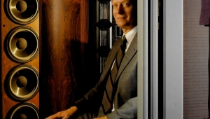
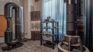
Hervé Delétraz's work bench, where his amplifier was designed and built.
Three years ago I finally decided to buy some simulation software. The prices had gone down, and I wanted to use my countless night hours in a more efficient way. I played with the software like a toy, using devices as if they were Lego pieces, making and destroying, rebuilding and simulating hundreds of elemental bricks, until I finally reached my goals. What a happy day, in July 1998, when I finally obtained a nice virtual circuit on my screen! It took about one year more to finalize the definitive schematics: only six bipolar devices per supply side from input to output, in three stages.
Three stages! Why so many, and why did it take so long to make such an amp when Nelson Pass made a single-transistor amp (I take my hat off, Mr. Pass!) years ago? Well, my design succeeded in almost every parameter I wanted, which is, alas, not obtainable with a single transistor.
The first stage behaves like a current buffer; i.e., the intrinsic input impedance is about 300k ohms, or more than most tube amps. It has no global or local feedback, only degenerative feedback. The second stage is the voltage gain stage. This stage has a gain of about 26dB, an intrinsic open-loop bandwidth of a few hundred kHz, and only two small, symmetrical local negative feedback loops. The third stage, the output stage, is a single push-pull pair driven in a particular fashion. I'll just say that the bias circuit doesn't feed the devices in the usual way, hence the possibility of avoiding the thermal compensation. Furthermore, this stage is free of all feedback, whether global or local or even degenerative. The output impedance is fair, at 0.28 ohms (remember, no NFB at all).
The other expected specs: 100Wpc into 8 ohms, 160Wpc into 4 ohms, 1Hz–500kHz @ –3dB, THD less than 0.5%, S/N 100dB(A). Sounds nice?
Next week: Hervé Delétraz builds a protoype of his amplifier design and sends several components to early graves.
Readers can contact Hervé Delétraz via e-mail at deletraz@bluewin.ch.
- Log in or register to post comments


| Loudspeakers Amplification Digital Sources | Analog Sources Accessories Featured | Music Columns Retired Columns | Show Reports | Features Latest News Community | Resources Subscriptions |
 © 2024 Stereophile
AVTech Media Americas Inc., USA
All rights reserved

