| Columns Retired Columns & Blogs |
Audio Research SP9 preamplifier
Following the introduction of their very expensive, tube/FET hybrid SP11 preamplifier, there were rumors that Audio Research was working on a hybrid tube/transistor preamplifier targeted to cost less than $2000. The rumors were confirmed when ARC showed a black-and-white photo of the SP9 at the 1987 Winter CES. Obviously, like all magazines, we were impatient to receive a review sample, but the first review of the SP9 actually appeared in the summer '87 issue of Peter Moncrieff's IAR Hotline. Peter's review was almost intemperately enthusiastic, comparing the SP9 positively with early samples of the SP11 and suggesting that its sound quality was considerably better than would be expected from its $1695 asking price. Naturally, we were anticipating good things when our review sample arrived in Santa Fe in late July.
Footnote 1: This hybridizing technique was first used in a similar but patented circuit by David Berning ten years ago in his TF-10 preamplifier. (You can guess what the T and the F stood for.)—J. Gordon Holt
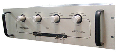
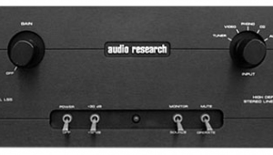
Like most other ARC watchers, I had assumed the SP9 would be a stripped-down version of the highly regarded $5000 SP11. And in the sense that it is rather more restrained in concept than the '11, it is just that. The one-piece unit (no separate power supply) has four knobs and four toggle switches vs the SP11's six and eight, respectively. There is only one volume control (vs the '11's two), but since it is located in the circuit right after the high-level inputs, there's no possibility of input-signal overload regardless of how strong the signal. ARC, however, denies that the 9 is a "stripped-down SP11," preferring to describe it as "an adaptation of some of the SP11's patented hybrid technology."
Well, it is and it isn't. Both are hybrid units, in that both have tubes and transistors in the signal path, but those components are combined rather differently in the two preamps.
In the SP11, each signal "stage" consists of a FET and a tube in a cascode configuration. This arrangement plays off the operating characteristics of both devices against each other, resulting in a combined performance better than either the FET or the tube on their own. The characteristic curve of an amplifying device is a graph which plots its through-current against the input voltage applied to its control gate (or grid). Ideally, through-current should be an exact function of input voltage, producing a characteristic "curve" that is a straight, diagonal line. In actuality, though, this "line" is more like a curve, with its ends fairly sharply curved and its middle section approaching but never quite becoming a straight line. Classic design practice has been to place the device's operating parameters on that mid-part of the line that has the least curvature, as this yields the lowest distortion. But because the line is never completely straight, the distortion is never zero.
The characteristic curves for a tube and a FET are interesting in that they are almost exact mirror images of each other: while one tends to curve in one direction, the other tends to curve in the other direction. Combining both devices into what is essentially a single amplifying stage has the effect of cancelling the curvatures of both, resulting in an almost perfectly straight transfer characteristic and, of course, vanishingly low distortion (footnote 1). Also worth noting is that the tubes in this kind of hybrid circuit are run in what's sometimes called "trickle mode." That is, their plate current is much lower than is usual for a tube, resulting in a product whose top panel, even after four hours' use, is barely warm to the touch. This means you don't have to give an SP11 (or the '9) as much ventilation space as is necessary with conventional tube preamps. It also means you can expect unusually extended tube life—ARC claims up to 10,000 hours of service life will be possible from the SP9 tubes!
By critical consensus, the SP11 is the best-sounding tube preamp Audio Research has ever made; certainly it has few, if any, peers. This is not that surprising, given that ARC has never made a less-than-excellent tube product, and that the hybrid cascode design should, in theory, be better than one with tubes alone. The SP9, however, features a rather different circuit topology. Almost identical gain blocks are used for both phono and line stages, the latter being less complicated, however, as it doesn't need as much gain, nor does it apply RIAA equalization. According to the supplied schematic, the circuitry is single-ended, operating from a single high-voltage rail. The input signal is applied to the gate of an n-channel FET, the drain of which is connected in a classic cascade manner to the grid of half of a 6dJ8 (ECC88) dual triode, biased by a resistive divider. In the phono stage, the plate (anode) of this tube feeds a pair of MOSFETS for additional gain, followed, like the line stage, by a MOSFET output driver, this AC-coupled to the volume control (phono) or main output (line). The output stage has a total of 20dB gain (a wire link on the board can be easily desoldered to lower the gain to 14dB, for use with more sensitive power amplifiers) with a single feedback loop around the FETs and tube. The phono stage has two overall loops, one AC, one DC, to provide the RIAA equalization. Components used are very high quality.
As with all ARC amplifiers, the power supply is sophisticated, with separately regulated supplies feeding the phono stage, the output stage, and the timing and muting circuitry. Power MOSFETs are used as the series pass elements. The transformer itself is a high-quality, electrostatically shielded toroidal type, fixed to the rear of the LH sidewall as far away from the phono circuitry as possible.
All the input and output sockets are gold-plated Tiffanys and the SP9 has inputs for four line-level inputs—Video sound, CD, tuner, and spare—in addition to inputs and outputs for two tape recorders. The phono input is nominally moving-magnet compatible; its very low noise makes it suitable for MCs with not too low an output and an internal resistor can be changed to lower the loading for MC cartridges. Input capacitance can also be changed appropriately. Upon turn-on, a timing circuit mutes the output for 45s, allowing the operating points to stabilize; the muting is performed with a relay which pulls the output to ground—the signal only flows through the potentially sound-degrading relay contacts when there is no sound!—a series resistor prevents excessive current flow through the output MOSFET when muted.
System
Before auditioning, I allowed the SP9 to warm up for a day or so, something I have found to be absolutely necessary before any new product will perform up to snuff. Other components used for my tests were the SOTA Star Sapphire turntable (with Electronic Flywheel), the Well-Tempered Arm, an Ortofon MC-2000 cartridge with its X-2000 step-up transformer, Threshold SA-1 power amplifiers, and Sound Lab A-3 full-range electrostatic speakers. Interconnects were the new Monster M-1000 Laboratory Reference series, and the speaker cables were by Straight Wire. Signal sources were from original 15ips tapes, CDs (from the Sony CDP-650ESD/DAS-703ES combo), and analog discs from Sheffield, Reference Recordings, Wilson Audio, and Opus 3 (the Depth of Image test record).
Footnote 1: This hybridizing technique was first used in a similar but patented circuit by David Berning ten years ago in his TF-10 preamplifier. (You can guess what the T and the F stood for.)—J. Gordon Holt
- Log in or register to post comments
