Zen & The Art of D/A Conversion

It has become accepted lore in audiophile circles that the 44.1kHz sampling rate adopted for Compact Disc is too low. Some writers have argued that, as a 20kHz sinewave will only be sampled about twice per cycle, it will not be reconstructed accurately, if at all.

Now, it may be true that 44.1kHz is too low a sampling rate, but certainly not for this reason. H. Nyquist, a researcher at Bell Labs, many years ago proved mathematically that as long as the sampling frequency is at least twice the highest frequency of interest in the signal to be sampled, the waveform will be accurately preserved. This was verified by JGH in his original review of the Sony PCM-F1 (Vol.5 No.7), but is hard to grasp emotionally---I mean two samples don't sound anything like enough! Here, then, is an elegant explanation I heard a little while ago, courtesy of Stanley Lipshitz of the Audio Engineerng Society and the University of Waterloo.

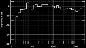
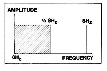
I'll start by assuming that we have something that doesn't exist: an audio signal with a spectrum that has no components above half the sampling frequency (fig.1). (Those who complain that picking a signal that doesn't exist to prove the case have a point; I will merely say that true scientific method always involves leaving out messy facts that confuse things unnecessarily. And you're going to get a few more such examples in this piece.)

Fig.1 Spectrum of input signal band-limited to half sampling frequency (s).

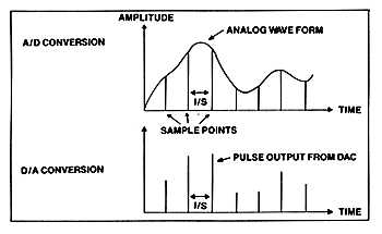
Using a perfect A/D converter---I told you there'd be more convenient simplifications---the signal is duly sampled and encoded, producing a mass of data consisting of a regular string of numbers. Each number describes how big the signal is at a time interval 1/s seconds after the last one ("s" is the sampling frequency). In order to reconstruct the signal, this stream of data is fed to a perfect D/A converter which, in its simplest form, spits out an infinitely narrow pulse every 1/s seconds, the height of the pulses roughly mapping out the original shape of the signal (fig.2).

Fig.2

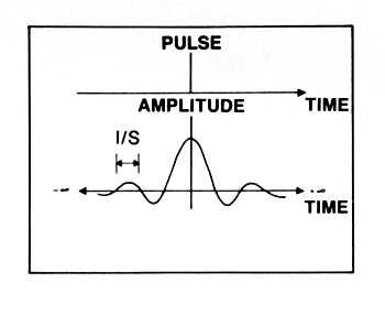
To reconstruct the waveform properly, we again need something that doesn't exist: a perfect low-pass filter with the impulse response shown in fig.3. Note that whereas we could imagine that somebody, somewhere, will eventually design a perfect A/D converter, this perfect filter's impulse response has a feature that doesn't exist in nature---ever! It appears to know that a pulse is about to happen---as with the mythical chemical substance postulated by Isaac Asimov that dissolved just before the experimenter added water. (Footnote 1) The perfect filter starts to oscillate with increasing amplitude before the pulse occurs. When the pulse finally happens along, the filter's oscillation reaches a maximum, then dies away in a perfect mirror image of its precognitive behaviour.

Fig.3 Perfect low-pass filter impulse response.

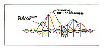
The actual shape of the response is called a (sin x)/x curve, and extends in time from minus infinity to plus infinity. As we are dealing with imaginary circuits, it is no sweat to define that the zeros in the (sin x)/x response---the points where the amplitude of the oscillations are zero---are spaced 1/s seconds apart. If we feed our stream of pulses of varying heights, representing the signal, into this filter, then each pulse will produce a (sin x)/x wave that will be zero every time another pulse comes along. It will not be zero in-between the pulses, as shown by fig.4, and if all these nonzero waves are added together, the sum of their amplitudes exactly reconstructs the shape of the original wave between the sampling points. I'll leave it to you to do the sums for a 20kHz sinewave sampled at 44.1kHz---give your PC a workout---but the important thing is that there is no missing information about the shape of the original waveform up to its bandlimit of 22.05kHz. Despite the fact that a 20kHz sinewave is only sampled twice per cycle. Elegance indeed---a marriage made in Heaven (or Bell Labs) between a perfect pulse stream and a perfect low-pass filter!

Fig.4 Waveform reconstructed by perfect low-pass filter.

But wait! This elegance exists only on paper. Our original signal doesn't exist; we used a perfect A/D converter; we assumed that the string of numbers didn't become corrupted in storage; our D/A converter produced infinitely narrow pulses, spaced exactly 1/s seconds apart; and our reconstruction filter featured a perfect impulse response extending to infinity in both time directions with zeros also spaced exactly 1/s seconds apart. On paper, everyone's CD player produces a perfect sound forever. In reality---well, this issue of Stereophile already contains enough discussions of the subjective shortcomings of the medium.

ARTICLE CONTENTS

COMMENTS
hollowman's picture

(Correct me as necessary...)

The "low-pass filter" in JA's above discussion is not the "oversampling digital filter" (which is, in all reality, optional) nor is it the SAME as the output low-pass filter (e.g., analog, multi-pole).

Rather, the "low-pass filter" in JA's above discussion, is a mathematical (on-paper, or theoretical) concept of digital-to-analog RECONSTRUCTION.

To put it plainly, if all you had was a bare-bones DAC chip (take one of the first-generation CD players with a chip like Philips TDA1540) -- so, no oversampling -- the above discussion of "low-pass filter", and (sin x)/x curve and impulse response would STILL apply.

I think the confusion comes from the rather liberal way the term "reconstruction filter" is used. I.e., sometimes used as an alternate to oversampling (e.g, 4x, or 8x) ... as well as the textbook terminology (as JA notes above), or here...

http://en.wikipedia.org/wiki/Reconstruction_filter

(Wiki seems to suggest that the RF can ALSO be the output analog filter, e.g., brick-wall, multi-pole, etc. AFTER the DAC chip)

Again I might stand well corrected!!
X