| Columns Retired Columns & Blogs |
Impressive DAC!
For the jitter measurements, curious what is the limit of the Miller Analyzer in terms of ps?
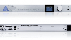
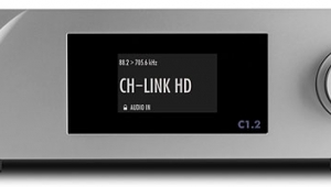
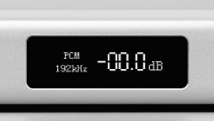
I used Stereophile's loan sample of the top-of-the-line Audio Precision SYS2722 system to measure the Weiss DAC202 (see www.ap.com and the January 2008 "As We See It"); for some tests, I also used my vintage Audio Precision System One Dual Domain and the Miller Audio Research Jitter Analyzer. As well as driving the DAC202 with AES/EBU and TosLink S/PDIF data from the Audio Precision analyzers, I used a MacBook running Mac OS 10.6.8 and Pure Music 1.8 to play test-signal files via FireWire, using the Weiss Control Panel and driver program to check such settings as sync source and sample rate. I used the front-panel control knob and display panel to make sure that each input (other than FireWire) was locked to the incoming datastream, and that the DAC202 wasn't performing any sample-rate conversion. For FireWire data, the DAC202 provides the master clock, but I found that I could get reliable operation only when using the FireWire port farthest from the left edge of the rear panel.
The DAC202 successfully locked to data with sample rates ranging from 32 to 96kHz via its TosLink input, and from 32 to 192kHz via AES/EBU, electrical S/PDIF, and FireWire. Input locking took up to several seconds with some sources, suggesting that the PLL of the DAC202's data input has only a narrow acceptance window, which will minimize datastream jitter. Using the test-tone files supplied on the setup CD and the Weiss processor's self-test routine, I found that it did indeed pass a bit-perfect output via FireWire, which I also checked by looking at the output from its AES/EBU port.
The output impedance was 22 ohms at all frequencies from the single-ended RCA jacks and 44 ohms from the balanced XLR jacks, both as specified. All three analog outputs—balanced, single-ended, headphone—preserved absolute polarity, the XLR jacks being wired with pin 2 hot. The maximum level from the balanced analog outputs was 0.4dB higher than specified at all four settings, at 1.11V ("1.06"), 2.22V ("2.12"), 4.34V ("4.15"), and 8.51V ("8.15"); the differences are trivial. The output levels from the RCA jacks were exactly half the balanced levels in each case, as expected. The maximum outputs from the front-panel headphone jack were 196mV ("0.2"), 949mV ("0.9"), 2.865V ("2.7"), and 5.45V ("5.2"). Again, the differences between the specified and actual levels are trivial.
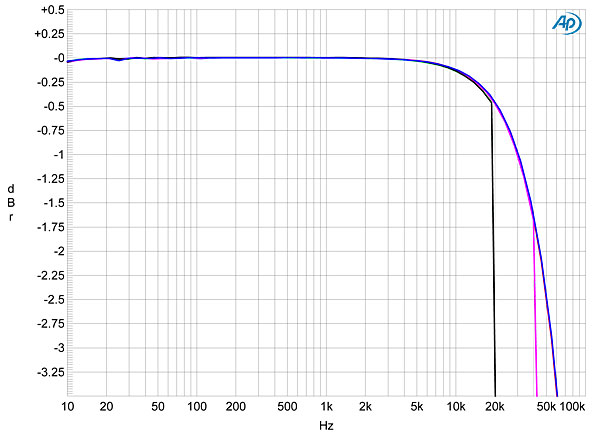
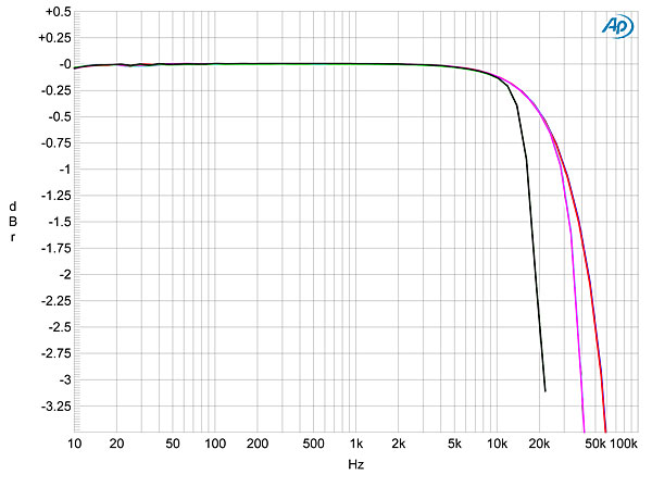
The DAC202's frequency response depended on which of the two reconstruction filters was selected. Fig.1 shows the response with Filter A with data sampled at 44.1kHz (green and gray traces), 96kHz (cyan, magenta), and 192kHz (blue, red). Other than a sharp rolloff just below half the sample rate with 44.1 and 96kHz data, all three responses conform to the same gentle rolloff above the audioband, down by 1dB at 30kHz at the higher rates. By contrast, with Filter B (fig.2), the responses roll off earlier, the 44.1kHz output down by 2.5dB at 20kHz but with less rejection between that frequency and the Nyquist frequency. Channel separation (not shown) was superb, at 125dB in both directions at 1kHz, and still 118dB at the top of the audioband.
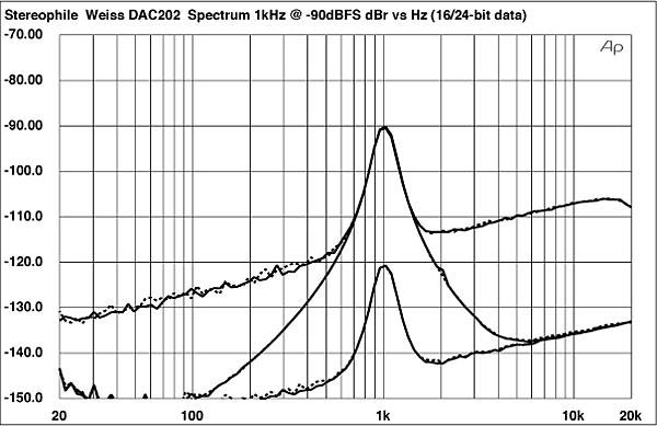
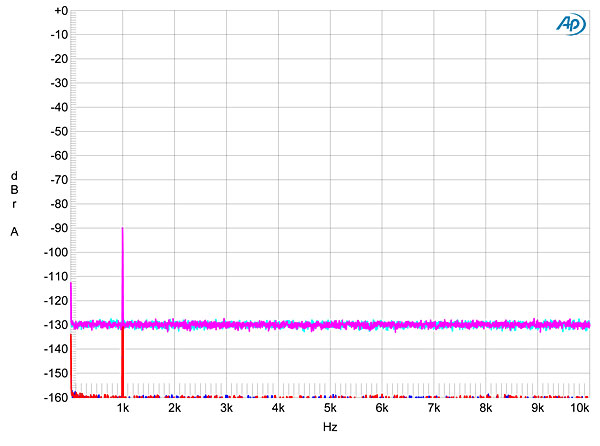
I tested the DAC202's resolution in my usual fashion, feeding it 16- and 24-bit data representing a dithered 1kHz tone at –90dBFS while sweeping the center frequency of a 1/3-octave bandpass filter from 20kHz to 20Hz; the resulting spectra, taken with the Weiss set to its highest output-level mode, are shown in fig.3. The traces peak at exactly –90dBFS, suggesting very low linearity error, with no distortion- or power-supply–related spuriae visible for 16- or 24-bit data. The increase in bit depth drops the noise floor by an extraordinary 29dB, implying 21-bit resolution, which both readily allows the Weiss to decode a tone at –120dBFS (bottom pair of traces), and is the highest I have ever encountered. Wow! This extraordinary resolution was confirmed by the FFT spectra in fig.4, which I plotted to –160dBFS rather than my usual –150dBFS, just to reveal the DAC202's noise floor. This was with the highest analog output level; setting it to the lowest level raised the noise floor by just 6dB, which is still superb resolution.
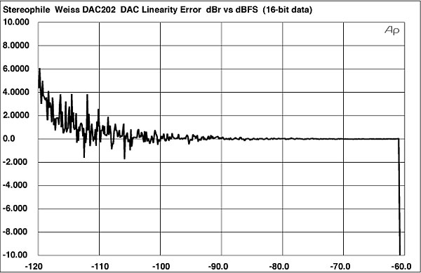
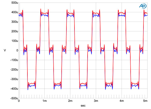
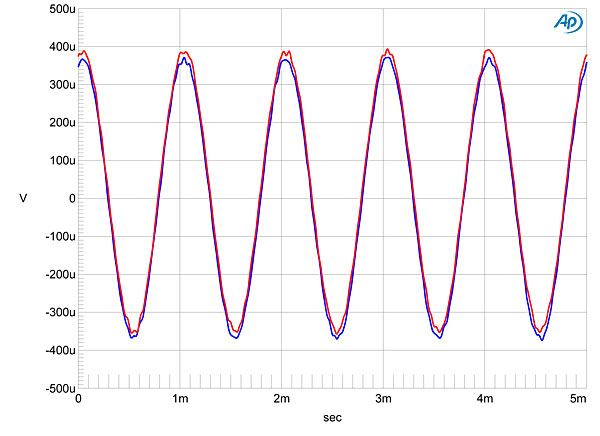
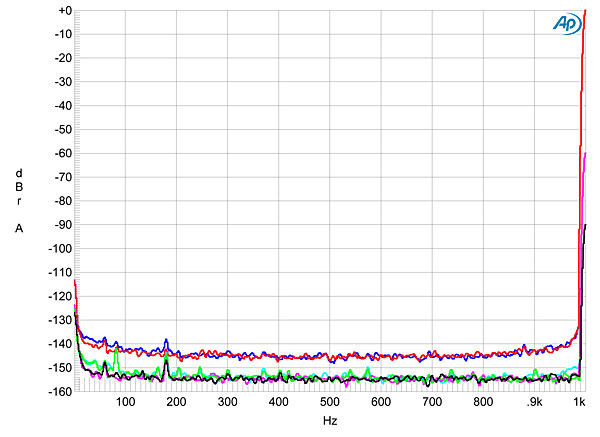
Looking at linearity error with 16-bit data (fig.5), there was minimal error to well below –110dBFS; in fact, all that could be seen was the recorded dither noise used to encode the signal. With this very low error and even lower noise floor, the DAC202's reproduction of an undithered 16-bit tone at exactly –90.31dBFS was essentially perfect (fig.6). Not only is the waveform superbly symmetrical, with the three DC voltage levels unambiguously defined, but the time-symmetrical Gibbs Phenomenon "ringing" is clearly evident. With 24-bit depth (fig.7), the Weiss produced a superbly defined sinewave, even without dither. Fig.8 shows the noise floor of the DAC202 set to its lowest output level and reproducing a 1kHz tone at 0dBFS, –60dBFS, and –90dBFS. Unlike some other DACs I have reviewed recently, the change in the level of the noise is due almost entirely to the gain-ranging of the Audio Precision's input amplifier.
As good as the DAC202's performance is in the digital domain, its analog output stage was just as good. Fig.9 shows its balanced output spectrum, set to its lowest gain and driving a full-scale 50Hz tone into 600 ohms. Other than the second, third, and fifth harmonics, all other spuriae are below –130dBFS (0.00003%), and the highest in level, the second, lies at just –114dB (0.0002%). Increasing the load to a more benign 100k ohms left the third harmonic at –120dB (0.0001%, not shown) but dropped the second harmonic to the same level, and the higher-order harmonics were now all below –133dB. This is an extraordinarily linear circuit!
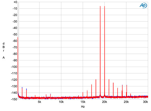
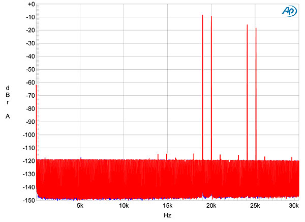
The Weiss DAC202's performance on the high-frequency intermodulation test depended on which filter was being used. Fig.10 was taken with the sharp-rolloff Filter A: intermodulation products are all below –120dB, and the aliasing products at 25.1 and 24.1kHz are well suppressed. However, with Filter B, which Erick Lichte preferred (fig.11), the ultrasonic images of the 19 and 20kHz tones are attenuated by only 10dB or so, and the noise floor rises to –120dB, which is equivalent to less than 15 bits of resolution. However, unlike some other products I have reviewed recently that use a similarly slow digital reconstruction filter, that noise floor isn't granular in nature and may well not degrade sound quality.
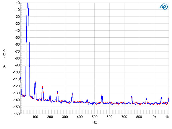
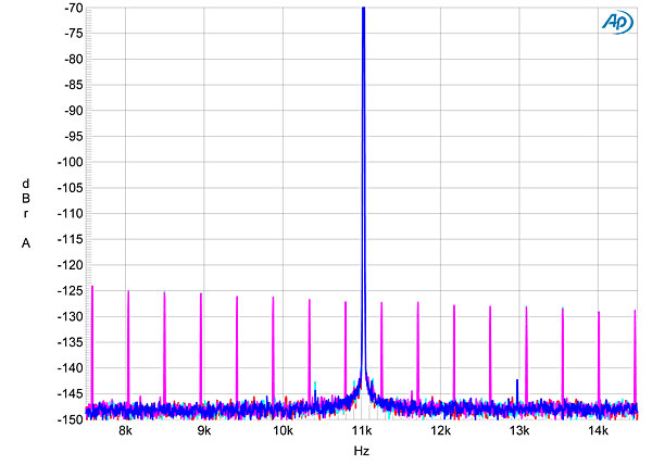
Finally, the Weiss DAC202 offers the best rejection of datastream jitter I have encountered. I have shown the spectrum of the processor's output when fed FireWire data representing 16- and 24-bit versions of the J-Test signal (fig.12). The AES/EBU and TosLink spectra are identical. With 16-bit data (cyan and magenta traces), the harmonics of the low-frequency, LSB-level squarewave were at the residual level, and were not accentuated or modified by the DAC202. With 24-bit data (blue, red), all that is visible is the central spike of the Fs/4 tone, this sharply reproduced, and with very little spectral spreading at its base. The jitter was too low for the Miller Analyzer to measure. Again: Wow!
The Weiss DAC202 is the best-measuring D/A processor I have measured in my quarter-century career at Stereophile. It just doesn't get any better than this!—John Atkinson
|
| ||||||||||

Impressive DAC!
For the jitter measurements, curious what is the limit of the Miller Analyzer in terms of ps?

What's it like with this? Everything else seems to measure very well, but you did not measure the impulse response.


| Loudspeakers Amplification Digital Sources | Analog Sources Accessories Featured | Music Columns Retired Columns | Show Reports | Features Latest News Community | Resources Subscriptions |
 © 2024 Stereophile