| Columns Retired Columns & Blogs |
Time Dilation, Part 1 Page 3
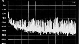
Hamstrung initially by conventional thinking, I began to conceive mechanical contrivances to hoist speakers (and the measurement microphone) 4.5m off the floor, so as to place them equidistant from the hall's floor and ceiling. That way, I should be able to open out the time window, for a 1m measurement distance, to around 23ms—much better than the 6ms or so I achieve at home, to be sure, but, as fig.2 clearly shows, still not enough. As the prospect of finding a room of significantly larger dimensions seemed remote, my thoughts turned to the various means of post-processing that have been proposed for removing reflections from speaker measurements (footnotes 5, 6)—but the prospect of getting them to work, and of verifying the accuracy of the results, looked daunting.
Footnote 5: P.D. Bauman, S.P. Lipshitz, A.C. Scott, J. Vanderkooy, "Cepstral Techniques for Transducer Measurement: Part II," Preprint 2302, Audio Engineering Society 79th Convention, October 1985.
Ground-Plane Measurements
It was on a trip to Harman International's headquarters in Northridge, California, last summer that a better, simpler approach hove into view. While on a whistle-stop tour of the JBL Professional division, I was shown the roof space where they perform bass measurements using Mark Gander's ground-plane technique, developed at JBL in the early 1980s (footnote 7). This is illustrated in its usual form in fig.4. Both the speaker and the microphone are placed on a hard (ie, reflective) planar surface, typically a large, flat roof (as at Northridge) or an empty parking lot.
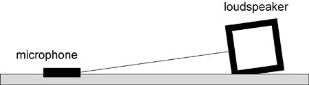
Fig.4 Mark Gander's ground-plane measurement technique. The hard, reflective surface acts as an acoustic mirror, but the close placement of the microphone to it postpones interference effects to high frequencies.
Effectively, there are now two microphones and two speakers involved in the measurement: the real microphone and speaker and their virtual partners, reflected in the acoustic mirror formed by the ground plane. But the close spacing of the microphone to the reflective surface means that this doubling up causes interference errors only at high frequencies; at low frequencies, the only downside is that the speaker now appears to have a baffle twice as wide as it actually is, which affects the measured response where diffraction effects begin to set in. Although this is something you have to be aware of when using this technique to measure frequency response, it's of no practical significance to my intended purpose of being able to measure cabinet resonances.
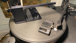
The ground-plane method is usually thought of as an outdoor technique, but there is no reason it cannot be used indoors, provided the floor is sufficiently reflective and a gated measurement technique is used to window out the wall and ceiling reflections. The prospect of using this approach in the community hall appealed to me for two reasons. First, it removes the need to contrive a means of precariously lifting speakers 4.5m off the floor. Second, by adopting the setup pictured in fig.5, the speaker is lifted from the floor, freeing up its panels to make their contribution to its normal resonance behavior—a speaker stand can also be included in the measurement. This arrangement puts the microphone off the normal listening axis, but that should not be a significant problem at the frequencies of concern here.
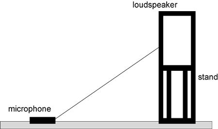
Fig.5 If you're prepared to accept an off-axis measurement, the ground-plane method can be adapted to allow full expression of cabinet resonances and include the effects of a loudspeaker stand.
I had also hoped that the ground-plane approach would offer a wider time window. So you can imagine my disappointment when, unable to recall the hall's width, I walked down the road to pace it out and found it to be about 10m, which meant a negligible improvement. More expletives.
More planes
It was a diagram of the source-image model of a loudspeaker in a room corner that prompted my realization that there is a straightforward way of extending the ground-plane method to advantage. Because it is usually an outdoor technique, it is normal to invoke only one reflective plane. But there is no reason the principle cannot be extended to two mutually perpendicular planes by placing the microphone at the junction of a wall and floor (fig.6), or even to three planes by placing it in a room corner. Depending on the room dimensions, one or other method will allow a considerable increase in the first-reflection arrival delay over the one-plane case. (Strictly, the delay to the first reflection is actually very short because the microphone is positioned close to but not flush with the reflecting surface(s). But let's not be pedantic—you know what I mean.)
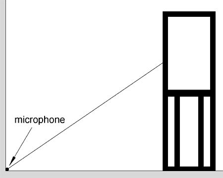
Fig.6 Two-plane extension of the ground-plane technique for use indoors, with the microphone placed at the junction of a wall and floor. In some cases the three-plane alternative—with the microphone in a room corner—allows the measurement time window to be opened out still further.
In the community hall, this approach makes a big difference to the achievable measurement time window. Placing the speaker and microphone halfway along the room's long wall should open it out to about 45ms—a figure that, with these room proportions, cannot be improved on by using a corner position instead. The principal practical requirement, as in the single-plane case, is that the two surfaces be almost perfectly reflective, which they are in this instance: a hardwood floor on a concrete base and a plastered brick wall. As far as physical setup is concerned, this is about the best I can ever hope to achieve.
But there may be another stratagem that can improve the results still further. In 1983, Laurie Fincham, then at KEF, presented two intriguing papers to the 74th AES convention in New York (footnotes 8, 9). The first described the subjective significance of a speaker's group-delay performance at bass frequencies, thereby predating Newell, Holland, and Mapp's recent observations by two decades. The second detailed how KEF had succeeded in achieving an accuracy of 1dB at 20Hz when using impulses to measure a speaker's full-space frequency response in a reverberant room measuring just 7.6m in all three dimensions—a space in which you would expect to achieve a frequency resolution of only 52Hz for a 1m measurement.
Without going into detail, KEF's method involves prefiltering the test signal to attenuate its LF content, so that the resulting impulse response from the speaker decays sufficiently quickly to avoid truncation effects due to time windowing. Appropriate correction is then applied to the resulting frequency response. Although KEF's system used an impulse test signal, there is no reason the same technique should not be applied to measurements made using the noise-like MLS signal—which opens up the intriguing possibility of combining the elaborated ground-plane setup with a prefiltered test signal, for even better results.
So far, this is only a thought experiment; I haven't yet tried either of these ideas in practice. But I've booked the community hall and have high hopes for the outcome. I'll let you know if they were realized when we next commune, in the April 2005 Stereophile.
Footnote 5: P.D. Bauman, S.P. Lipshitz, A.C. Scott, J. Vanderkooy, "Cepstral Techniques for Transducer Measurement: Part II," Preprint 2302, Audio Engineering Society 79th Convention, October 1985.
Footnote 6: L. Larsson, K. Dalbjörn, M. Kleiner, "Reduction of Room Effects in Loudspeaker Measurements," Preprint 4967, Audio Engineering Society 106th Convention, May 1999.
Footnote 7: M.R. Gander, "Ground-Plane Acoustic Measurement of Loudspeaker Systems," JAES, Vol.30 No.10, October 1982 (see also the correction in Vol.34 No.1/2, January-February 1986).
Footnote 8: L.R. Fincham, "The Subjective Importance of Uniform Group Delay at Low Frequencies," Preprint 2056, AES 74th Convention, October 1983.
Footnote 9" L.R. Fincham, "Refinements in the Impulse Testing of Loudspeakers," Preprint 2055, AES 74th Convention, October 1983.
|
| |||||||||
- Log in or register to post comments


| Loudspeakers Amplification Digital Sources | Analog Sources Accessories Featured | Music Columns Retired Columns | Show Reports | Features Latest News Community | Resources Subscriptions |
 © 2024 Stereophile
AVTech Media Americas Inc., USA
All rights reserved

