| Columns Retired Columns & Blogs |
I read it while sitting in my ribbon chair.
The Timbre had a low maximum output voltage, measuring just 1.36V from the single-ended outputs marked "Main." The single-ended outputs labeled "Buffered" produced a whopping 6.7V, a result of the additional buffer amplifier driving this output. The balanced outputs had a maximum output voltage of 2.7V. Source impedance was a low 52 ohms from the "Main" outputs, 500 ohms from the "Buffered" outputs, and 104 ohms from the balanced outputs. The much higher output impedance from the buffered outputs is incongruous; Timbre suggests the "Buffered" output should be used to drive a power amplifier directly through a passive level control. Although 500 ohms is a moderate figure, a lower output impedance on the "Buffered" outputs would seem more appropriate. DC level at the "Main" outputs was a low 7mV from both the left and right jacks, increasing to 36mV from the "Buffered" outputs. DC at the balanced jacks was between 9mV and 10mV. The Timbre doesn't invert absolute polarity from either the main or buffered outputs, and the XLR output jacks are wired with pin 2 "hot."
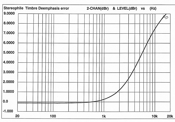
Fig.1 is the Timbre's frequency response and de-emphasis error. The frequency response is unusually shaped, with the midrange and treble shelved down very slightly in relation to the bass. The difference is only 0.2dB, but this will be audible over such a wide bandwidth. The sonic result of this measured response could be a slight darkening of the sound. This is exactly what JS and I heard in the auditioning.
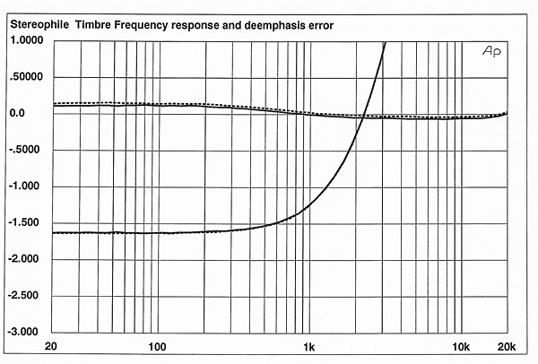
The most salient feature of fig.1 is, however, the huge de-emphasis error seen in the bottom traces. Although you can't tell how severe the de-emphasis error is with our usual 0.5dB/division scale, I included it on the frequency-response plot for continuity with our other graphical presentations. Fig.2 is more illustrative: The de-emphasis error is more than +7dB at 10kHz. I initially thought that the de-emphasis equalization wasn't being switched in, but the Timbre's de-emphasis error doesn't quite match the pre-emphasis curve. This suggests that the Timbre's de-emphasis circuit is engaging, but that the rolloff is wrong, perhaps due to a wrong-value capacitor or resistor. During the auditioning, I suspected the Timbre's de-emphasis circuit wasn't engaging; pre-emphasized discs, such as Three-Way Mirror (Reference RR-24CD), sounded extremely bright.
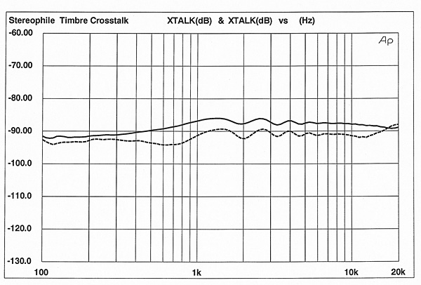
The Timbre's crosstalk performance is shown in fig.3. The channel separation was better than 85dB across the audio band—competent but not outstanding performance.
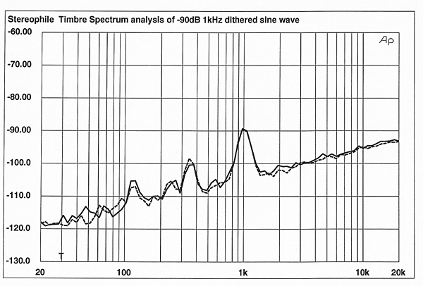
A spectral analysis of the Timbre's output when decoding a –90dB, 1kHz dithered sinewave (fig.4) revealed some power-supply noise in the audio circuit. This is seen as the peaks at 120Hz and 240Hz. Although the peak between 300Hz and 400Hz appears to be power-supply related (360Hz), later measurements show that it's actually a peak of energy in the noise floor. The overall noise level of fig.4 is higher than in many processors I've measured, particularly below 500Hz.
A wider-band spectral analysis (200kHz) of the Timbre's output when driven by a code of all zeros produced the lower pair of traces in fig.5. The noise level is low, although the power-supply noise can still be seen. Because the CS4328 DAC is a noise-shaping type, I expected to see a rise in noise above the audio band. When I didn't, I suspected that the DAC's output is turned off when the input signal was all zeros.
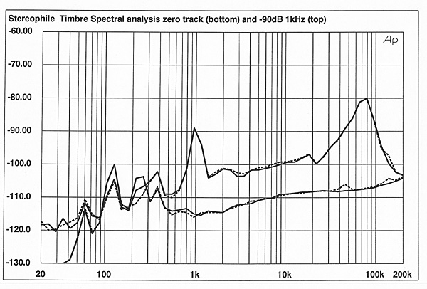
This was indeed the case, shown by the top pair of traces—a spectral analysis of the Timbre's output when decoding a –90dB, 1kHz dithered sinewave. The noise floor rose significantly, and the effects of the CS4328's noise shaping can be seen as the rapid rise in noise above the audio band. Note that the top traces look less smooth than those in fig.4 (the same measurement), because the same number of data points were spread over a wider bandwidth.
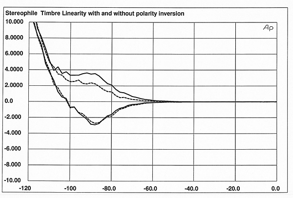
The Timbre's linearity changed when the front-panel polarity-inversion switch was pressed. With no polarity inversion, the Timbre appeared to have a slight negative error between –80dB and –100dB. With the polarity inversion engaged, there was a positive error. I attribute this to a higher noise level with the polarity switch engaged, which dominated the linearity measurement. Fig.6 is the Timbre's linearity, with and without the polarity switch engaged, plotted on the same graph.
The Timbre's reproduction of an undithered, 1kHz sinewave at –90dB is shown in fig.7. Note the rather high level of audio-band noise overlaying the stepped waveform. The Timbre's noise-modulation performance (fig.8) was less than impressive. The traces, which show the Timbre's noise floor with five different input levels from –60dB to –99dB, diverge significantly below 2kHz, with wide separation below 1kHz. This means that the Timbre's noise floor shifts in level and changes in spectral distribution as a function of input signal level. The shifts are as great as 6dB, far higher than the 2dB of noise-modulation shifts reported in the literature to be audible. Notice also the large peak between 300Hz and 400Hz, which I mentioned earlier as not being power-supply noise. The fact that the peak in this band changes in amplitude with signal level, and the relatively wide-band nature of the noise, suggest that the noise between 300Hz and 400Hz is an artifact of the DAC.
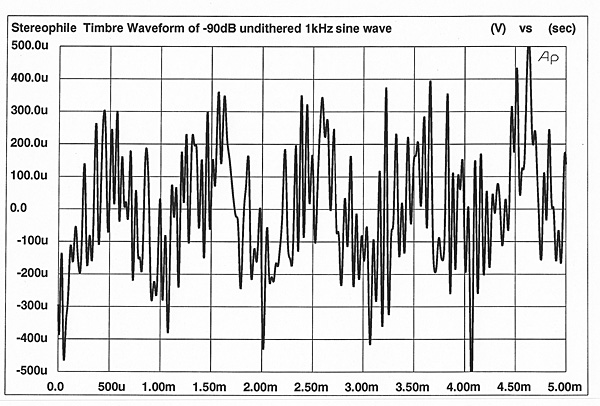
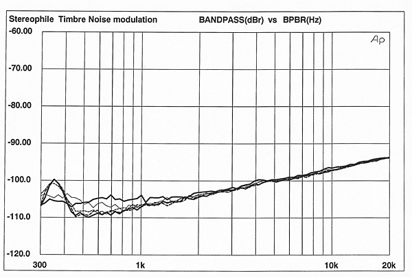
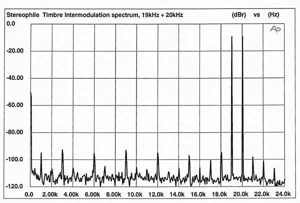
Fig.9 is the Timbre's intermodulation spectrum when driven by a full-scale mix of 19kHz and 20kHz. The IM products, seen as spikes at 1kHz and multiples of 1kHz, are moderately high in level and numerous. More than eight intermodulation products rise higher than –100dB.
Because the Timbre's chassis is factory-sealed and cannot be opened, I couldn't measure its jitter performance.
Finally, the review sample had a few glitches; eg, pressing the input selector button sometimes caused it to jump from input 1 to input 3. This can be caused by contact bounce, in which one press of the button causes the switch contacts to engage more than once, making the switch think it's been pressed twice.
When switching between sampling frequencies to make sure the Timbre would lock to 32kHz and 48kHz (it did), the Timbre would lose lock and not regain it unless the input selector was taken off the active input, then moved back to the active input. In addition, the Timbre produced a high-frequency whine when there was no music playing—a classic example of an idling tone (footnote 1) Though it could be heard through the loudspeakers, it wasn't very loud, and it could not be heard at all when music was present.
Overall, the Timbre's technical performance was less than impressive. The large de-emphasis error, presence of low-frequency noise, high levels and number of intermodulation products, and the functional glitches didn't inspire confidence in the design.—Robert Harley
|
| ||||||||||

I read it while sitting in my ribbon chair.

I had written to ask how to pop out the rear small panel to get to the fuses but finally got it. The slot for a small screwdriver is below and to the side of the panel.


| Loudspeakers Amplification Digital Sources | Analog Sources Accessories Featured | Music Columns Retired Columns | Show Reports | Features Latest News Community | Resources Subscriptions |
 © 2024 Stereophile