| Columns Retired Columns & Blogs |
Threshold T2 preamplifier Measurements
Sidebar 3: Measurements
A full set of measurements was run on the Threshold T2 in its balanced mode, with selected measurements repeated in the unbalanced configuration. Unless otherwise noted, the results below are for the balanced mode.
The output impedance of the T2 at its line outputs measured 314 ohms (70 ohms unbalanced). Its (line) input impedance measured 10.6k ohms (just a little less unbalanced at 10.2k ohms). The above figures are for the left channel at the maximum setting of the gain control; the right-channel results were not significantly different, nor were the results with the level control set at unity (–19) or lower. The output impedance at the tape output was just under 110 ohms regardless of the input source impedance—indicating a buffered tape output.
The DC offset at the T2's outputs measured a highish 13.5mV in the left channel, 20.4mV in the right, balanced or unbalanced. The preamp is non-inverting from its inputs to its main outputs, and in the balanced mode, pin 2 is positive, pin 3 negative. Maximum line-stage gain (aux input to line output) measured 19.1dB in either the balanced or unbalanced mode.
The volume-control tracking of the T2 was excellent; both channels matched to well within 0.1dB except at the lowest levels, and even then (at –60dB), the variation just barely exceeded that figure. The signal/noise (reference 1V) was 90.1dB (82.2dB unbalanced) from 22Hz to 22kHz, deteriorating to 77.2dB (66dB unbalanced) over a wider, 10Hz–500kHz bandwidth. The latter improved to 95.1dB (90.1dB) when A-weighted.
Both in balanced and unbalanced modes, the T2's frequency response (fig.1) was flat in the audioband, –0.1dB at 40kHz. Fig.2 is a plot of the crosstalk; though the result is somewhat better in one channel, it's still excellent—and audibly insignificant—in both.
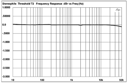
Fig.1 Threshold T2, balanced frequency repsosne at 1V into 100k ohms (0.5dB/vertical div.).
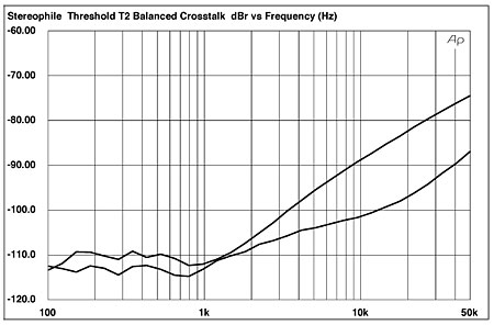
Fig.2 Threshold T2, crosstalk (L–R, top at 10kHz) (10dB/vertical div.).
The line THD+N vs frequency for the T2 is shown in fig.3 (200mV input). The distortion is insignificant across the range, though marginally higher in the unbalanced mode. Note that the input level chosen, 200mV, is not the level producing the absolutely lowest THD+N at 1kHz. It is, however, an input that produces 1.8V output—a level that's more than enough to drive most amplifiers to full power. And if that output voltage isn't high enough, the T2 can provide a lot more before distortion becomes a problem. (It reached 1% THD+N at 1kHz at an output of 25.4V!) Its THD+N vs output (at 1kHz) is plotted in fig.4. Suffice to say that distortion is no limitation here.
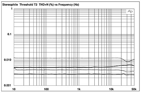
Fig.3 Threshold T2, THD+noise (%) vs frequency at 200mV input into 100k ohms.
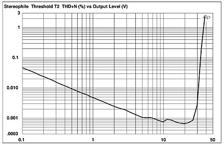
Fig.4 Threshold T2, distortion (%) vs output voltage into 100k ohms.
Finally, fig.5 shows a plot of the spectrum resulting from a 50Hz input at an output level of 1.8V into 100k ohms. While the third and fifth harmonics (150Hz and 250Hz) are more prominent than the second and fourth (100Hz and 200Hz), they're so far down in level (below –90dB, or under 0.003%) as to be of no concern whatsoever.
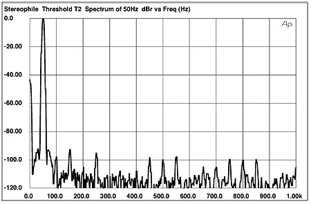
Fig.5 Threshold T2, spectrum of 50Hz sinewave, DC–1kHz, at 1.8V into 100k ohms.
The T2's test-bench results were excellent. There's nothing here to compromise its potential for first-rate audible performance.—Thomas J. Norton
|
|
| ||||||||||
- Log in or register to post comments


| Loudspeakers Amplification Digital Sources | Analog Sources Accessories Featured | Music Columns Retired Columns | Show Reports | Features Latest News Community | Resources Subscriptions |
 © 2024 Stereophile
AVTech Media Americas Inc., USA
All rights reserved

