| Columns Retired Columns & Blogs |
Theta DS Pro Generation V digital processor Measurements
Sidebar 2: Measurements
The Generation V's maximum output level when decoding a 1kHz, full-scale sinewave was 7.06V from the balanced outputs, 6.62V from the unbalanced outputs. These are very high levels, but remain in line with Theta's tradition of whopping output levels. This high output level is, however, much lower than the Gen.III's 14V output level, which approached the point of overloading the inputs to some preamps.
The output impedance was very low, measuring 27 ohms from the balanced jacks and 18 ohms from the single-ended outputs. The combination of high output level and low output impedance makes the Gen.V a good candidate for use with a passive level-control.
I measured no DC offset at the balanced jacks, and just 0.1mV from the single-ended outputs. The Gen.V doesn't invert absolute polarity unless the front-panel switch is in the "180°" position.
In my review of the Theta Gen.III in October 1992 (Vol.15 No.10), I noted that the unit didn't properly decode signals with sampling frequencies other than 44.1kHz (32kHz and 48kHz data). Similarly, the Gen.V would lock to those sampling frequencies, but the analog output was unstable. This may be a moot point—most users will never need 32kHz or 48kHz decoding.
Fig.1 shows the Gen.V's frequency response and de-emphasis error. The V's custom filter produces a negligible 0.2dB rolloff at 20kHz. The de-emphasis error also produces a rolloff of 0.2dB at 20kHz, but starts rolling off a little sooner. The interchannel crosstalk plot (fig.2) shows excellent channel separation. The left and right channels were nearly identical, with 107dB of separation at 1kHz, decreasing at 6dB/octave to 80dB at 20kHz.
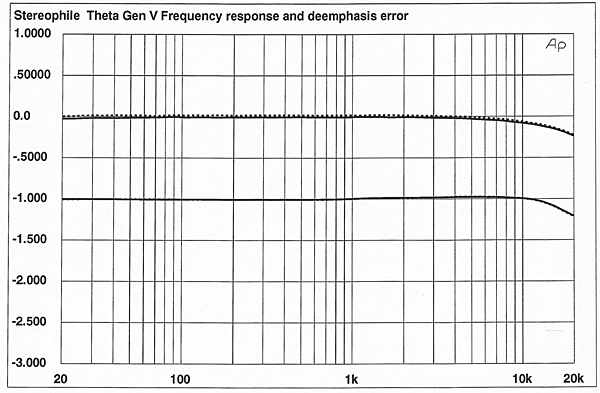
Fig.1 Theta DS Pro Generation V, frequency response (top) and de-emphasis error (bottom) (right channel dashed, 0.5dB/vertical div.).
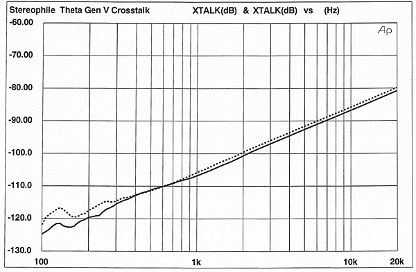
Fig.2 Theta DS Pro Generation V, crosstalk R–L (L–R dashed, 10dB/vertical div.).
A spectral analysis of the V's output when decoding a 1kHz dithered sinewave at –90dB (fig.3) shows the processor to have low noise, good DAC behavior, and no spurious artifacts. We can see, however, just a trace of 120Hz power-supply noise in the right channel, but it's well down in level (–117dB). With a wider measurement bandwidth (200kHz) and an input signal of all zeros (fig.4), we can see the filter's steep rolloff above the audioband, and, again, that trace of power-supply noise.
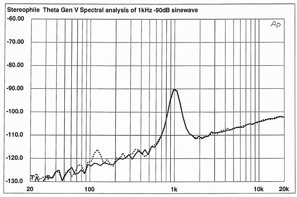
Fig.3 Theta DS Pro Generation V, spectrum of dithered 1kHz tone at –90.31dBFS, with noise and spuriae (1/3-octave analysis, right channel dashed).
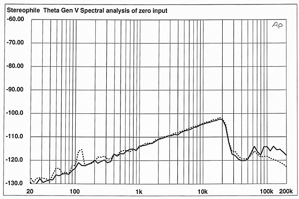
Fig.4 Theta DS Pro Generation V, spectrum of digital silence, with noise and spuriae (1/3-octave analysis, right channel dashed).
The Gen.V's linearity (fig.5) was excellent—the Burr-Brown PCM 63 DACs used in the V have intrinsically good linearity, due to their technique of shifting the zero-crossing point away from bipolar zero. The PCM 63 needs no MSB trimming, and will maintain its good linearity over time. The age of MSB trimmers and severe linearity errors seems to be drawing to a close.
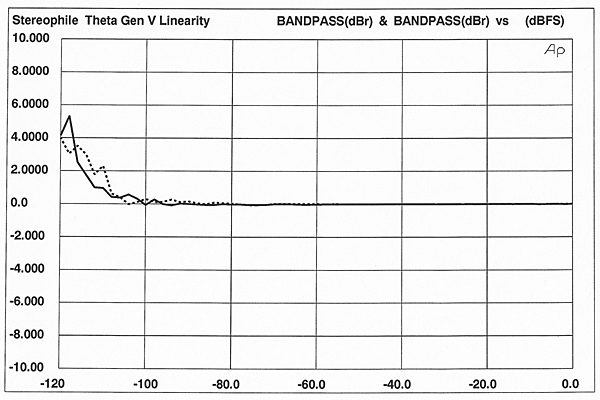
Fig.5 Theta DS Pro Generation V, departure from linearity (right channel dashed, 2dB/vertical div.).
The V's reproduction of a low-level waveform (a 1kHz, –90dB undithered sinewave) was excellent (fig.6). The noise level is very low, the signal has very little glitch energy, and the step size is uniform. The Gibbs Phenomenon "ringing," due to the 20kHz bandwidth restriction, can easily be seen.
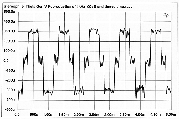
Fig.6 Theta DS Pro Generation V, waveform of undithered 1kHz sinewave at –90.31dBFS.
The noise-modulation performance (fig.7) was excellent, with tight trace groupings. The noise floor at an input level of –60dB, shown by the solid trace, deviates from the other traces below 400Hz, which indicates that the noise floor's spectral content shifts very slightly at this input level.
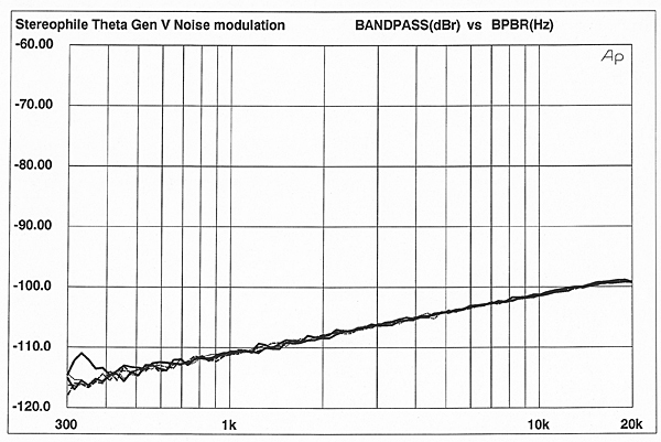
Fig.7 Theta DS Pro Generation V, noise modulation, –60 to –100dBFS (10dB/vertical div.).
The Gen.V produces the best-looking intermodulation spectrum I've measured in a digital processor (fig.8). The 1kHz difference component lies at –106dB—phenomenal performance. Moreover, there are almost no other IM components generated when the V reproduces a full-scale mix of 19kHz and 20kHz; those that exist are very low in level.
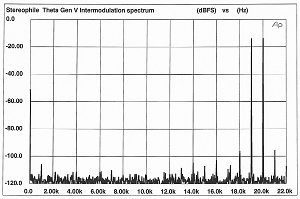
Fig.8 Theta DS Pro Generation V, HF intermodulation spectrum, DC–22kHz, 19+20kHz at 0dBFS (linear frequency scale, 20dB/vertical div.).
I measured the Gen.V's word-clock jitter on the 352.8kHz word-clock input to the DAC. With a 1kHz, full-scale sinewave, the RMS jitter value, measured over a 400Hz–22kHz bandwidth, was 145 picoseconds. The jitter spectrum is shown in fig.9. Note the absence of signal-correlated jitter, which would be seen as spikes in the plot. The Gen.V's jitter is the more benign random jitter.
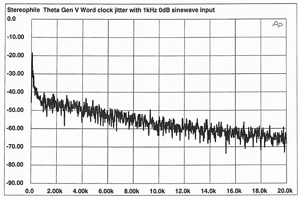
Fig.9 Theta DS Pro Generation V, word-clock jitter spectrum, DC–20kHz, when processing 1kHz sinewave at 0dBFS (linear frequency scale, 10dB/vertical div., 0dB=1ns).
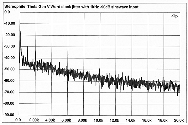
Fig.10 Theta DS Pro Generation V, word-clock jitter spectrum, DC–20kHz, when processing 1kHz sinewave at –90dBFS (linear frequency scale, 10dB/vertical div., 0dB=1ns).
With an input signal of all zeros, the jitter decreased slightly, and the trace (not shown) was perfectly clean. Driving the Gen.V with a 1kHz, –90dB sinewave produces low levels of signal-correlated components at 1kHz and 2kHz, but the spectrum is otherwise clean. The RMS jitter level with the jitter-inducing low-level signal was 165ps. Overall, the Gen.V's jitter level was reasonably low, free from periodic jitter, and didn't change that much as a function of input level.—Robert Harley
NEXT: Specifications »
|
|
| ||||||||||
- Log in or register to post comments


| Loudspeakers Amplification Digital Sources | Analog Sources Accessories Featured | Music Columns Retired Columns | Show Reports | Features Latest News Community | Resources Subscriptions |
 © 2024 Stereophile
AVTech Media Americas Inc., USA
All rights reserved

