| Columns Retired Columns & Blogs |
..and I think he is a genius, but when all these companies are using the same basic modules(I think that Jeff Rowland uses it also), aren't they all building pretty much the same basic amp?
I performed a full set of measurements using Audio Precision SYS2722 system (see www.ap.com and the January 2008 "As We See It"). As the Theta Prometheus has a switching output stage that produces ultrasonic noise that would overload the Audio Precision's input circuitry, I carried out most of the tests using, ahead of the analyzer, an Audio Precision AUX-0025 passive low-pass filter. Usually, before measuring an amplifier, I run it for an hour at one-third power into 8 ohms—the most thermally stressful condition for a class-B output stage. But as the Prometheus has a class-D output, that preconditioning is irrelevant. Even so, I subjected serial number 050085 to this test to ensure that it had settled into its long-term operating condition. (The chassis was slightly warm at the end of this period.)
The Theta's voltage gain into 8 ohms was the same, at 27.7dB, for its balanced and unbalanced inputs, and the amplifier preserved absolute polarity for both inputs (ie, was non-inverting); its XLR jack is wired with pin 2 hot. At 90k ohms, the balanced input impedance was very close to the specification of 94k ohms at low and middle frequencies, though it dropped to 84k ohms at the top of the audioband. The unbalanced input impedance was half these values.
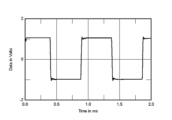
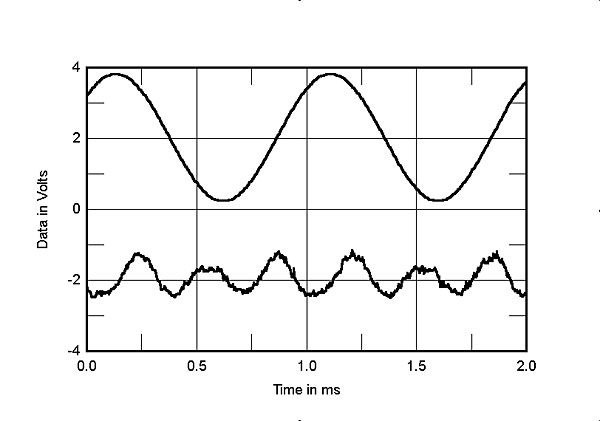
The Prometheus's output impedance was 0.11 ohm at 20Hz and 1kHz, rising slightly at 20kHz to 0.13 ohm. The modification of the Theta's frequency response, which results from the interaction between this impedance and the impedance of our standard simulated loudspeaker, was very low (fig.1, gray trace). This graph also shows that the ultrasonic rolloff doesn't change significantly as the load impedance drops to 2 ohms, with a –3dB point of 40kHz. However, a small peak at 77kHz becomes a little more pronounced into higher impedances. Without the Audio Precision low-pass filter, the Theta's reproduction of a 1kHz squarewave into 8 ohms is obscured by switching noise (fig.2). With the filter, however, this noise is eliminated (fig.3), and a 10kHz squarewave can be seen to have a small degree of overshoot that correlates with the slight response peak at 77kHz (fig.4). Commendably, however, no ringing is associated with this overshoot.


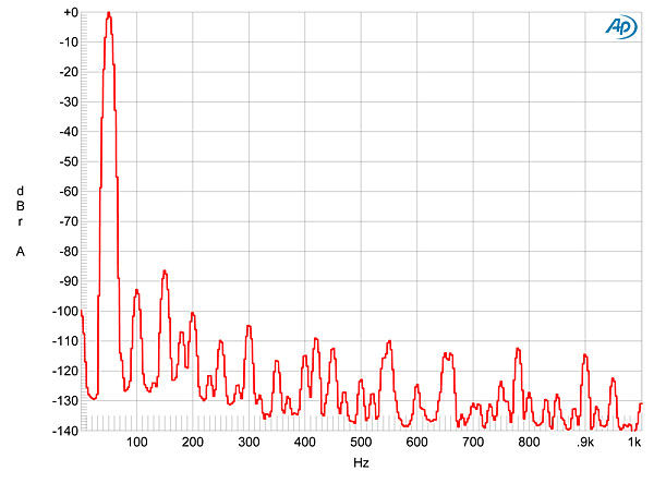
Without the Audio Precision low-pass filter, and with the Theta's input short-circuited, there was 321mV of ultrasonic noise present in the amplifier's output, with a center frequency of 453kHz. With the filter, the unweighted, wideband signal/noise ratio, ref. 2.83V into 8 ohms, was 76.3dB, this improving to an excellent 94dB when the measurement bandwidth was restricted to the audioband—and improving even more, to 95.6dB, when the measurement was A-weighted. With the amplifier passing signal, however, there was the noise level depended to some extent on the output power. Fig.5, taken with the auxiliary AP low-pass filter (LPF) (as were all the subsequent graphs), shows low-frequency spectra of the Theta's output while it reproduced a 1kHz tone at 1W (blue trace), then 100W (red), into 8 ohms. Spuriae are present at the AC-related frequency of 60Hz and its odd harmonics, which increase with the power level. This behavior usually suggests magnetic interference from the amplifier's power transformer, but as the spuriae are still all at or below –110dB (0.0003%) at the high power, their presence will be of only academic interest.
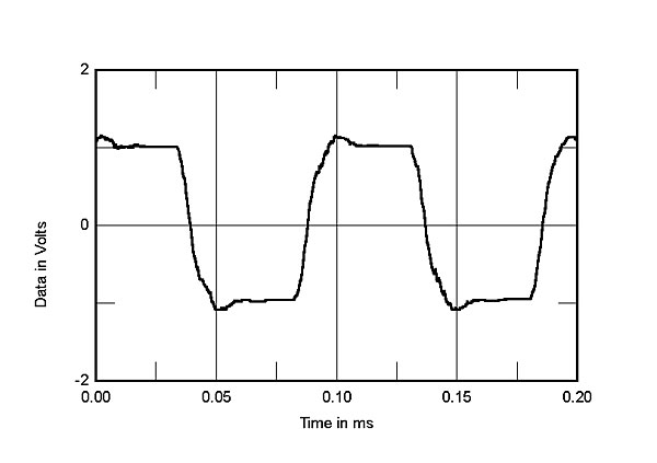
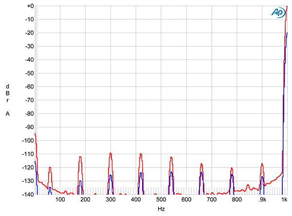
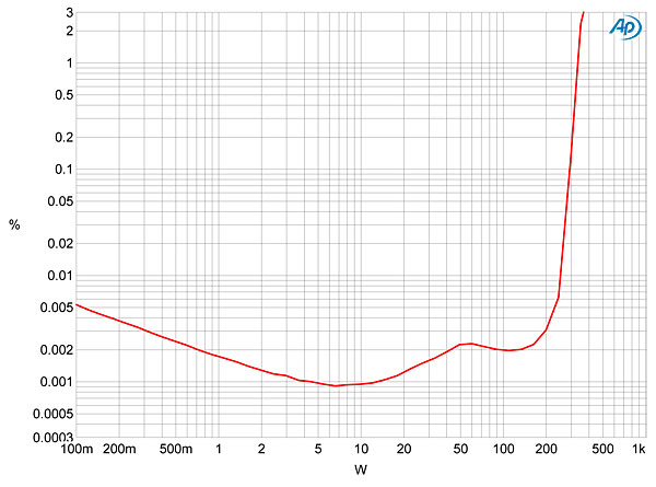
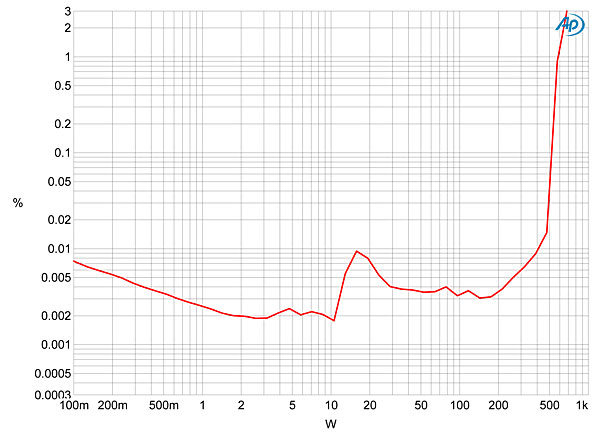
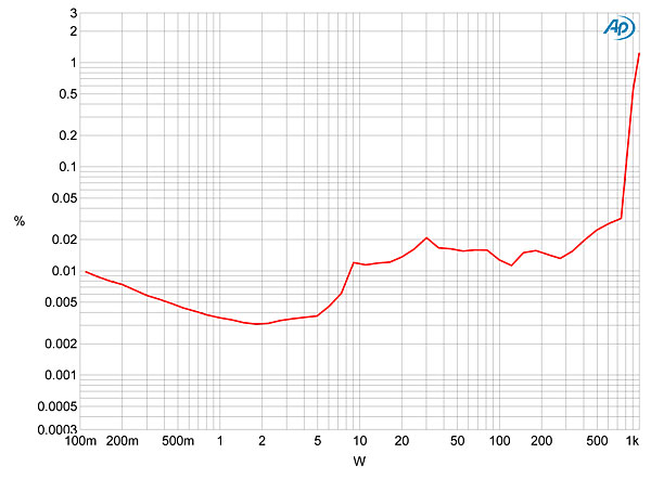
Fig.6 reveals that the Theta's distortion starts to rise above the audioband noise floor just below 10W into 8 ohms, but remains below a low 0.003% until the start of actual waveform clipping. Even then, the rise in THD is relatively gradual, and the amplifier doesn't reach 1% THD until 320W (25.05dBW), just over 1dB higher than the rated 250W into 8 ohms (24dBW). Into 4 ohms (fig.7), the Prometheus delivers 600W (24.8dBW) at 1% THD rather than the specified 500W, though this graph shows that the amplifier is less linear below clipping into this load. Into 2 ohms (fig.8), the Theta still easily exceeded its specified maximum power of 850W, delivering 980W (23.9dBW). (The wall voltage was 123.4V during these tests.)
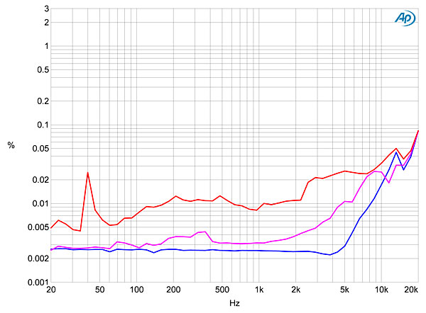
To be sure I was looking at distortion rather than noise, I examined how the percentage of THD+noise changed with frequency at a fairly high level, 20V, equivalent to 50W into 8 ohms. Fig.9 reveals that the Prometheus is still very linear below the mid-treble region at this level, even into 4 ohms (magenta trace). However, the distortion rises considerably into 2 ohms (red), and in the top two octaves into the higher impedances, though it still remains below 0.08%.
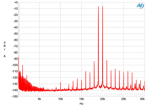
Into 8 ohms at moderately high power, the distortion is predominantly third harmonic (fig.10), though at just 0.0024%, this, again, will be of only academic interest. As the current increases, the third harmonic is joined by even-order harmonics (fig.11), but these are all at lower levels. Intermodulation distortion is also very low, even at high powers into 4 ohms (fig.12), with the 1kHz difference product associated with tones at 19 and 20kHz lying 100dB below the peak signal level (0.001%).
The measured performance of Theta Digital's Prometheus is superb, even for an amplifier with a class-D output stage. It's similar to that of the more expensive MBL Corona C15 monoblock, which I reviewed in June 2014, which shouldn't be surprising—the MBL also uses a custom version of the Hypex output module designed by the very talented Bruno Putzeys.—John Atkinson
|
|
| ||||||||||

..and I think he is a genius, but when all these companies are using the same basic modules(I think that Jeff Rowland uses it also), aren't they all building pretty much the same basic amp?
sys2722 has AES17 filters use those to test Class D amps stop using AUX-0025 on AP2.
Theta Digital Prometheus Distortion 0.01 at 15 watts?
Is that a joke? John Fix Your Measurements Chain!
I have tested alot of ICE power amps and Stereophile data always has more than 10x distortion than the real world data.
AP1 and AP2 inputs will not distort from switching residual only the Autorange circut will trigger wrong scale and you use AES17 filter to fix that, and for frequency response you do not use filters of any kind only Distortion Measurments needs AES17.
PS. IM graph is not correct and Freq Response is from the AUX-0025 not the amp.

John Atkinson
Editor, Stereophile
John i did a prototype with NC1200 modules and got identical graph as Hypex datasheet i dont use AUX0025 at all only AES17 the switching residual will not induce slew rate distortion (unless it has so badly design filter that will not pass FCC regulation), maybe Theta Digital has that bad input stage that adds high frequency distortion, noise and roll off ill try to borrow one to test it.
The distortion nubmers on 4 ohm are terrible for this kind of amp maybe the power supply transformer is too small and the noise performance is crap.
I can upload images but they are the same as the official datasheet. Cheers J.
hypex.nl/docs/NC1200_datasheet.pdf
Edit.
PS. I need to mention for non technical audiophiles when using AES17 filter distortion data are only valid up to 6 khz because AES17 filter is a 20khz filter design to measure Sigma Delta DAC's, from 6 - 50khz is covered by 19+20kHz Intermod distortion measurments (you can use 19+20khz IMD data as equivalent to 20khz sine wave distorion measurments only instead of looking at the spectrum above 20k the distorion commponents will mirror back inside the audio band and you can use 20khz bandwidth for less noise there is no need to use some new "super hyper oscilloscope" thats the beauty of it) and switching residual is not somekind of wierd noise, it looks like a parabolic shapes up and down string together something like sinewave but with parabolic halfs and is in milivolts the tweeters are up to hundreds of ohms at 400khz cant even fell anything let alone distort so no worries.
When you Measure the amp with AP2 and you start at microvolts the Autorange circut will see mili volts and yell to his buddy DSP hey there is voltage comming get going change the scale! and the low level data is not usefull, there is no distortion no wierd thing going on people need to relax AP recommends AUX passive filter because there is a nutjobs that run Class D without filters and try to measure it that way that amp my frends is broken, that can be a good test for John if it need AUX-0025 That amp is Broken :) and AP1 needs AUX-0025 because it does not have proper AES17 module slot. I forgot to trasmit 400khz you need 750 meters of speaker cable so dont worry about RF offcourse there are horrible designs that wipeout all the radio staions in the area but it is not because off the speakers cable emmits at 400khz its because amp pushes Mhz's into it, amps modules like B&O Ice power and Hypex have non of the problems.
Cheers.
John.. thanks for the detailed review. Its nice to know that Class D technology has matured to the point of being considered in high end audiophile amplifiers. I have one concern in your measurements, but by placing an external 20kHz filter that doesn't exist in real life, you make the measurements of the amplifier look better than they should be. The effect of these high energy ultra-sonics on the distortion numbers is masked. What effect would they have on actual loudspeaker systems? Why not make the measurements with the default 80kHz bandwidth of the AP test system?
Why not make the measurements with the default 80kHz bandwidth of the AP test system?
First, because with hundreds of millivolts of ultrasonic noise present, any THD+Noise measurement will be dominated by that noise, even with the 80kHz measurement bandwidth. Second, that ultrasonic noise will drive the AP's input stage into slew-rate limiting, generating additional distortion.
John Atkinson
Editor, Stereophile
So should we have no concerns for these ultra sonics on our loudspeaker systems or radiated emissions to other electronics in our AV systems? BTW, what is the frequency of this ultrasonic noise, which I presume would be the switching frequency of the amplifier?
So should we have no concerns for these ultra sonics on our loudspeaker systems or radiated emissions to other electronics in our AV systems?
Not necessarily. Remember that hooked up to the amplifier's class-D output stage is an antenna - the speaker cable. This, of course, is loaded by the speaker, which presents a low impedance at audio frequencies. But above 100kHz, the speaker may well present a very high impedance, due to the voice-coil inductance of the tweeter. So depending on the length of the cable and the ultrasonic impedance of the speaker, the residual switching noise may well be re-radiated into the environment, as well as finding its way into the system ground, which will depend on the amplifier design and circuit layout. All these factors are unpredictable.
BTW, what is the frequency of this ultrasonic noise, which I presume would be the switching frequency of the amplifier?
It tends to be between 400kHz and 500kHz.
John Atkinson
Editor, Stereophile
I appreciate the answers John. Thank you :)

An interesting article, thank you. A comparison to the similarly priced Merrill amp using the same rather popular N-Core module would have been an interesting implementation comparison.

I would be happy to provide a pair of the Merrill Audio VERITAS Monoblocks for the comparison. I have also offered Stereophile the Merrill Audio VERITAS Monoblocks for review.
Perhaps there could be an independent, neutral place where the A/B comparison is done side by side. I understand some have done the side by side comparison and hope they will share their findings.
Would love to get a non biased opinion about these two amps?


| Loudspeakers Amplification Digital Sources | Analog Sources Accessories Featured | Music Columns Retired Columns | Show Reports | Features Latest News Community | Resources Subscriptions |
 © 2024 Stereophile