| Columns Retired Columns & Blogs |
JA, can you remember or have filed away what that measurement was on the Technics GaN flagship SU-R1 or the SU-R1000?
Cheers George
The Technics SU-G700M2 appears to be a less powerful, less–well-equipped sibling of the Technics SU-R1000 integrated amplifier that KM reviewed in December 2021, which offered superb measured performance. I measured the SU-G700M2 with my Audio Precision SYS2722 system, and as the amplifier has an output stage that resembles class-D, I inserted an Audio Precision AUX-0025 passive low-pass filter between the test load and the analyzer. This filter reduces RF noise that would otherwise drive the SYS2722's input circuitry into slew-rate limiting. (Without the filter, there was 720mV of ultrasonic noise, with a center frequency of 67kHz, at the amplifier's output terminals.) I used the filter for all the loudspeaker output tests, other than frequency response.
I looked first at the Technics's performance via its single-ended line inputs. The SU-G700M2 preserved absolute polarity at all outputs with Phase set to Normal. The volume control operated in accurate 0.5dB steps, and the maximum gain at the loudspeaker outputs was 42dB. (The optional 20dB attenuation was bypassed for this measurement.) At the preamplifier output, the gain was 21.3dB, and at the headphone output it was 26.7dB. The SU-G700M2's power amplifier stage can be accessed separately: It offered a fixed gain of 32.4dB. The input impedance at both the line inputs and the power amplifier inputs was 32k ohms at 20Hz and 1kHz, with an inconsequential drop to 28.3k ohms at 20kHz.
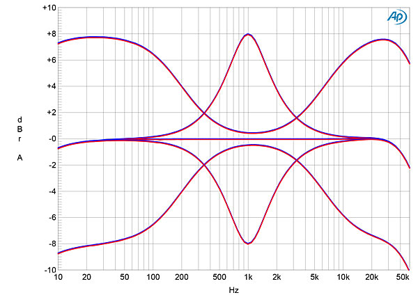
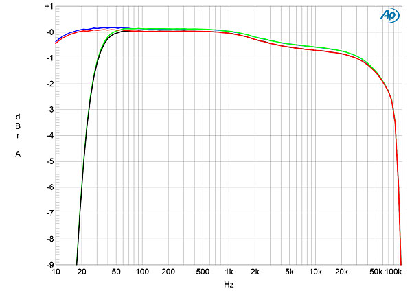
The Technics amplifier's output impedance at the headphone output was a relatively high 66 ohms. At the preamplifier output, it ranged from 781 ohms at 20Hz to 707 ohms at 20kHz. It was difficult to measure the output impedance at the loudspeaker terminals due to an increase in ultrasonic noise with no load connected, even with the Audio Precision low-pass filter in circuit. But the modulation of the amplifier's frequency response due to the Ohm's law interaction between the SU-G700M2's source impedance and the impedance of my standard simulated loudspeaker was a low ±0.25dB in the bass and midrange (fig.1, gray trace), which implies that the output impedance, including the series impedance of 6' of spaced-pair loudspeaker cable, must have been close to a low 0.1 ohm.
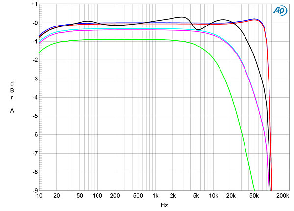
The response into an 8 ohm resistive load (fig.1, blue and red traces) extended to 70kHz but rolled off rapidly above that frequency. With a 4 ohm resistive load (cyan and magenta traces), the output started to roll off slowly in the top audio octave, reaching –3dB at 45kHz. Into 2 ohms (green trace), the output was down by 3dB at 20kHz, presumably due to an increase in output impedance in the top audio octave. This graph was taken with the volume control set to –12dB. The excellent channel matching was preserved at other settings of the control.
Like the SU-R1000, the SU-G700M2 has the LAPC function, which is intended to compensate for the dependence of a loudspeaker's impedance with frequency. I bypassed LAPC for these measurements, but its effect can be seen in fig.2 in the SU-R1000's measurements.
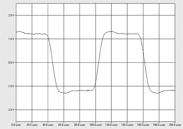
There is a small, critically damped overshoot in the Technics's reproduction of a 10kHz squarewave's leading edges into 8 ohms (fig.2). The absence of Nyquist-frequency ringing from an antialiasing filter suggests either that the SU-G700M2 doesn't digitize its analog inputs or that the output stage's low-pass filter removes the ringing, meaning that the A/D converter operates at 192kHz. Its tone controls offer a maximum boost and cut of close to 8dB (fig.3).
Channel separation was good, at 75dB in both directions. With the auxiliary low-pass filter and the amplifier loaded with 8 ohms, its inputs shorted to ground, and the volume control set to its maximum, there was still 330mV of ultrasonic noise present in its outputs. The SU-G700M2's unweighted, wideband signal/noise ratio was therefore just 18.5dB ref. 2.83V in both channels. Audio Precision, though, recommends using a brick-wall filter such as the AES17 filter included on the AP 2720 when testing noise in class-D amplifiers. When that filter was employed, the signal/noise ratio improved to 64.6dB; A-weighted, the S/N ratio was 67.7dB.
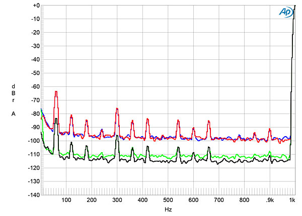
Spuriae at the supply frequency of 60Hz and its harmonics were present in the amplifier's output; their levels depended on the setting of the volume control. The blue and red traces in fig.4 were taken with the volume control set to its maximum. Reducing the volume by 20dB significantly lowered the levels of both the supply-related spuriae and random noise (green and gray traces).
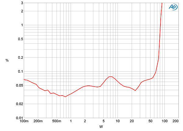
Technics specifies the SU-G700M2's maximum power as 70Wpc into 8 ohms and 140Wpc into 4 ohms, both powers at 0.5% THD and both equivalent to 18.45dBW. We specify clipping power as when the THD+noise reaches 1%. By that measure, and with both channels driven, the Technics amplifier clipped at 80Wpc into 8 ohms (fig.5, 19.03dBW) and 148Wpc into 4 ohms (fig.6, 18.7dBW). I didn't test clipping power into 2 ohms, as the amplifier isn't specified into that load.

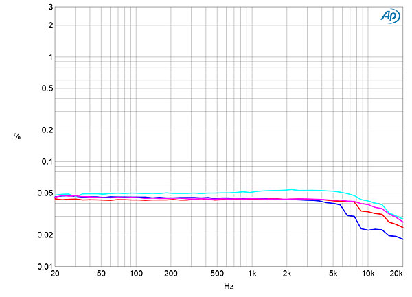
The distortion is low at low powers, so I examined how the THD+N varied with frequency at 12.65V, equivalent to 20W into 8 ohms and 40W into 4 ohms (fig.7). To prevent the residual ultrasonic noise from contaminating the THD+N reading, I used an additional brickwall low-pass filter set to 40kHz. This filter affected the THD+N reading for signals above 5kHz, but the distortion is very similar into both 8 ohms (blue and red traces) and 4 ohms (cyan and magenta traces), at close to 0.05%.
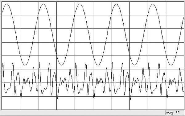
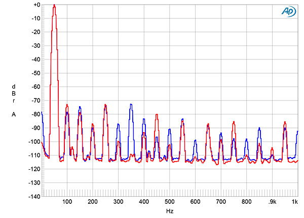
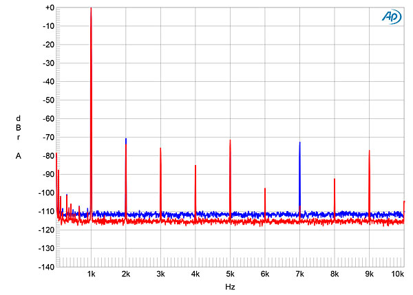
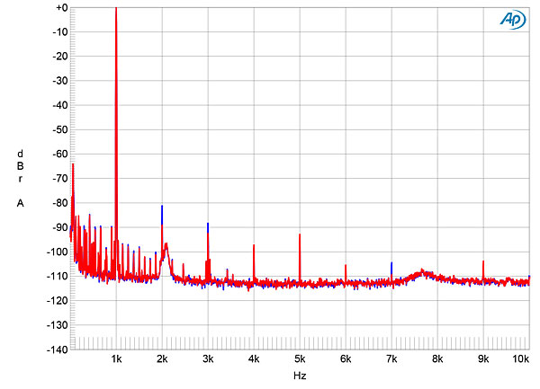
The distortion waveform at this output voltage (fig.8) suggested the presence of high-order harmonics. This was confirmed by spectral analysis (figs.9 & 10): The fifth harmonic in both channels, the seventh harmonic in the left channel (blue trace), and the ninth harmonic in the right channel (red trace) were almost as high in level as the second and third harmonics. Although these harmonics are low in level, lying between –80dB (0.01%) and –70dB (0.03%), they could be audible at high listening levels in the region where the ear is most sensitive. Tested with an equal mix of 19 and 20kHz tones at 20W peak into 8 ohms, the intermodulation distortion products all lay at or below –80dB (fig.11). At the same output voltage into 4 ohms (not shown), the higher-order products were slightly lower in level, but the second-order difference product at 1kHz rose to –74dB (0.05%).
I looked at the Technics SU-G700M2's digital-input performance using its S/PDIF inputs, then repeated some of the tests with the USB input. The SU-G700M2's optical input locked to S/PDIF data sampled up to 96kHz, the coaxial input to data sampled up to 192kHz. Apple's AudioMIDI utility revealed that the USB inputs accepted 24- and 32-bit integer data sampled at rates up to 705.6kHz. (This is the capability of the USB receiver chip; Technics specifies the SU-G700M2's USB input as operating up to 368kHz.) Apple's USB Prober utility confirmed that the USB port operated in the optimal isochronous asynchronous mode.
The Technics's digital inputs all preserved absolute polarity. With the volume control set to its maximum, a 1kHz digital signal at –40dBFS resulted in a level at the preamplifier output of 256.9mV, at the headphone output of 480.8mV, and at the loudspeaker outputs of 2.77V. The latter voltage implies that digital data at 0dBFS will drive the amplifier into clipping. For the digital input measurements, therefore, I used the Menu to activate the –20dB input-attenuator setting. Even so, digital data at 0dBFS caused the amplifier to turn off after briefly showing the message "F76" on its front-panel display. The manual explains that this message means that "An abnormality has occurred. ... The protection circuit is activated, and the power may be turned off automatically." To avoid damaging the power amplifier stage with high-level digital data, I examined the digital inputs' behavior at the headphone output, which mutes the loudspeaker output.
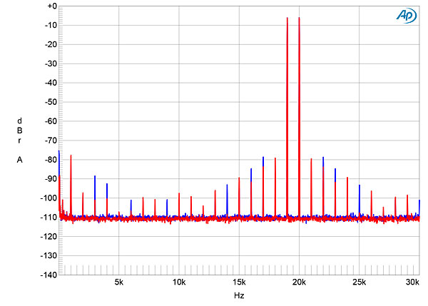
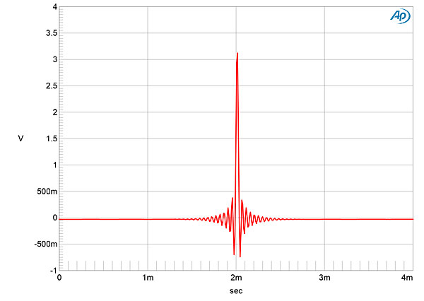
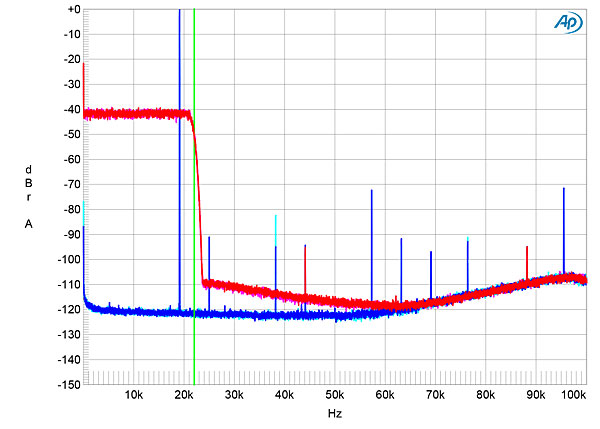
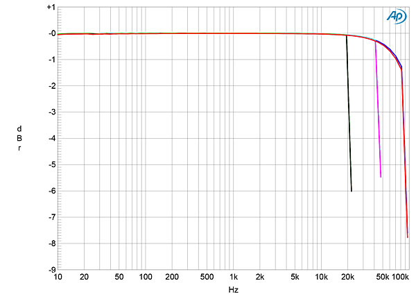
The impulse response with 44.1kHz data (fig.12) indicates that the reconstruction filter is a conventional linear-phase type, with time-symmetrical ringing on either side of the single sample at 0dBFS. With 44.1kHz-sampled white noise (fig.13, red and magenta traces), the linear-phase filter's response rolled off sharply above 20kHz, reaching full stop-band suppression at 24kHz, just above half the sample rate (vertical green line). The aliased image at 25kHz of a 19.1kHz tone at 0dBFS (blue and cyan traces) is suppressed by 90dB, and the highest-level distortion harmonic of the 19.1kHz tone, the third, lay just below –70dB (0.03%). The digital-input frequency response was flat in the audioband, then rolled off sharply above half of each sample rate (fig.14). The levels of the two channels matched perfectly.
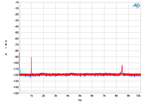
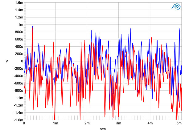
To examine the ultimate resolution of the SU-G700M2's digital inputs, I disabled the 20dB attenuation, set the volume control to its maximum, and examined the spectrum at the headphone output with a dithered 1kHz tone at –90dBFS with 16- and 24-bit data (fig.15). There was no reduction in the noisefloor with 24-bit data, which implies that the SU-G700M2 offers 16 bits' worth of resolution. The reason for this limited resolution can be seen in fig.16, which shows the waveform of a tone at exactly –90.31dBFS with undithered 16-bit data. Although the headphone amplifier is analog, the three DC voltage levels described by the data are completely obscured by high-frequency noise, presumably radiated from the switching output stage. With undithered 24-bit data (fig.17), what should have been a relatively clean sinewave was again obscured by high-frequency noise. It should be noted, however, that the noise is above the audioband.
Intermodulation distortion via the Technics amplifier's digital inputs (not shown) was low, the second-order difference product at 1kHz lying at –84dB (0.006%) in the left channel and –93dB (0.0025%) in the right. While the higher-order products were higher in level, they were at or below –70dB (0.03%).
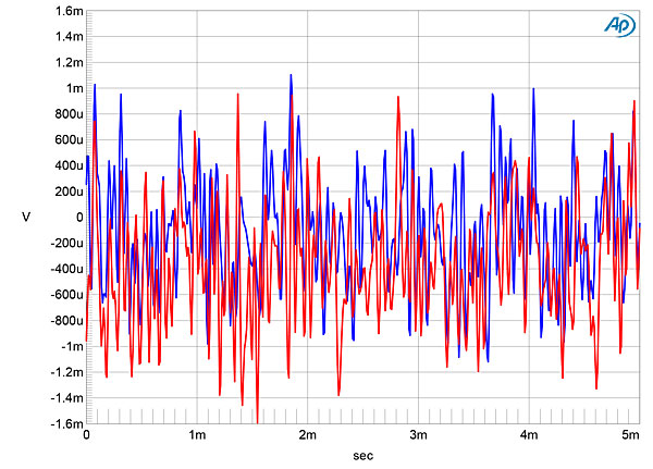
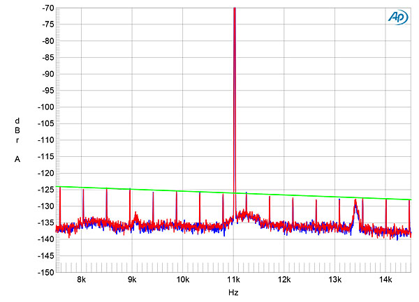
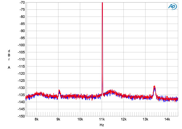
I tested the SU-G700M2 for its rejection of word-clock jitter via its TosLink and USB inputs, using 16- and 24-bit J-Test data sampled at 44.1kHz. All the odd-order harmonics of the 16-bit J-Test signal's LSB-level, low-frequency squarewave were close to the correct levels (fig.18, sloping green line), though some modulation of the noisefloor is evident. As expected from fig.16, the 24-bit noisefloor (fig.19) was no lower in level than that in fig.18.
Turning to the SU-G700M2's phono input, I followed the manual's advice to connect a separate ground wire from the terminal on the amplifier's chassis to the ground of the Audio Precision analyzer. I primarily examined the phono input's behavior at the headphone output, again to avoid damaging the amplifier's output stages with high-level signals.
The Technics's phono input preserved absolute polarity in both moving magnet and moving coil modes. Set to MM, the phono input had a maximum gain of 57.7dB at the preamp outputs, 63.1dB at the headphone outputs, and 78.4dB at the speaker outputs. Set to MC, the phono input's maximum gains were 78.7dB, 84.1dB, and 99.4dB, respectively. These values mean that clipping is possible at the outputs with high-level phono signals, so it would be best to use the optional 20dB attenuation. The phono input's input impedance, set to MC mode, was an appropriate 120 ohms across the audioband; set to MM, the input impedance was 39k ohms at 20Hz and 1kHz, falling to 32k ohms at 20kHz.
The SU-G700M2's RIAA correction (fig.20) was well-matched between the channels with a slight downward shelf in the treble. The switchable subsonic filter (green and gray traces) rolled off the response by 6dB at 20Hz. The MM phono input's unweighted, wideband S/N ratio, measured with the input shorted to ground and with the volume control set to –6dB, was 35.6dB (average of both channels) referred to an input signal of 1kHz at 5mV. This low ratio was due to the presence of ultrasonic noise, presumably radiated from the switching output stage; restricting the measurement bandwidth to 22Hz–22kHz increased the ratio to an excellent 84dB, while switching an A-weighting filter into circuit further increased the ratio to 88.3dB. The MC input's ratios were 14–16dB lower due to this mode's higher gain.
The Technics phono input's overload margins, measured with the volume control set to –30dB to avoid clipping the headphone output, were usefully high from 20Hz to 20kHz, at 16.9dB ref. 1kHz at 5mV, MM, and 16.9dB ref. 1kHz at 500µV, MC. The phono stage's distortion was very low, with all the harmonics at or below –80dB (0.01%, fig.21). High-order intermodulation distortion with an equal mix of 19kHz and 20kHz tones, at a peak input level equivalent to 1kHz at 5mV, lay at –70dB (not shown), with the second-order difference product at 1kHz lying at –84dB (0.005%).
While the SU-G700M2 meets its specified power and has a phono input that offers respectable measured performance, especially in its high overload margins, the contamination of the analog phono stage and headphone outputs with ultrasonic noise and the high-order harmonics in the outputs were disappointing.—John Atkinson
|
| ||||||||||

JA, can you remember or have filed away what that measurement was on the Technics GaN flagship SU-R1 or the SU-R1000?
Cheers George

JA, can you remember what that measurement was on the Technics GaN flagship SU-R1 or the SU-R1000?
The SU-R1000 had 316mV of ultrasonic noise present at the loudspeaker outputs without the auxiliary Audio Precision low-pass filter. I didn't note the center frequency.
John Atkinson
Technical Editor, Stereophile
J.A.:"the three DC voltage levels described by the data are completely obscured by high-frequency noise, presumably radiated from the switching output stage. With undithered 24-bit data (fig.17), what should have been a relatively clean sinewave was again obscured by high-frequency noise. It should be noted however that the noise is above the audioband."
I would think that if the reviewer listen close he would have heard "artifacts" of this almost 1v noise through such efficient speakers as the 96dB DeVore Fidelity Orangutan O/96??
Cheers George

this is really depressing

Listen to what the man, JA, said.
I said "artefacts" of the fundamental.
(disappointing was used by him, not me)
Cheers George
“I compared the Technics's digital conversion to that of the Denafrips Ares II DAC, using a Sonore opticalRendu to convert the Ethernet stream to USB, the external DAC's output connected to one of the Technics's line inputs.”
Did you have occasion to play DSD files from the opticalRendu over the USB input? If so, did they play natively or did they play as DoP? I ask because I am having a tough time finding integrated amp USB inputs that can play native DSD without an ASIO driver, which Linux-based renderers like the Rendus cannot use.
Sonore has added some DAC IDs to its kernel, which is supposed to be the workaround, but I have found the implementation to be hit-or-miss. (For example, my ultraRendu is supposed to have the DAC ID for the NuPrime IDA-8’s DAC, but I can’t get dsf’s to play natively at all. That’s not necessarily an issue with DLNA players such as JRiver, Audirvāna, or MinimServer, but, with the expensive HQPlayer, I not only can’t upsample PCM to DSD, I end up with DSD downsampled to PCM.)
I know I can get external DACs that do just fine with USB and DSD from Linux, but, due to cabinet space considerations, I am in the market for an integrated that can handle these files natively.

I love reading all the reviews of Stereophile, it's a joy.
In al reviews this sentence in this review is one of the weirdest, puzzling and original ones I came across in years:
" translating analog to digital as smoothly as Rudy Van Gelder sipping a martini"
Haha, it should be added to the audiophile dictionary I suggest. But before that, shouldn't it be between quote signs because it is by Technics ? And what does it mean ?
Thank you
Hi JA,
Interesting measurements. How was the SU-G700M2 connected to the power supply? Was it plugged directly in the wall? Or connected to an EMI/RFI filter device?
The reason I ask is because when I hooked up the SU-G700M2 to an EMI/RFI device, there was a low humming noise coming out of the speakers but only when the input was set to MAIN (in my setup the SU-G700M2 provides 2 channel/front speakers to a Marantz Cinema 50), all the other inputs were dead silent. So, I connected the SU-G700M2 directly to the wall and the noise was gone.
Interesting measurements. How was the SU-G700M2 connected to the power supply? Was it plugged directly in the wall? Or connected to an EMI/RFI filter device?
I always test products plugged directly into the wall outlet.
John Atkinson
Technical Editor, Stereophile
Thanks for answering my question. I have another question about what you said in the measurements "The latter voltage implies that digital data at 0dBFS will drive the amplifier into clipping.".
This is so true because mine clips constantly if I listen loud (100-102 db peaks). It is driving me crazy (although I don't listen at over 100db, sometimes I do unintentionally - the music has a surge - and then it clips).
There is no fix for this, right?
I still have the Arcam SA-20, would I be better off with it?
Thanks!
An update: Owners have complained about the F76 has happened constantly for them too and not just at over 100db, even using the dimmer makes the unit shutdown with a F76. I saw there is a firmware update, I'll apply it.


| Loudspeakers Amplification Digital Sources | Analog Sources Accessories Featured | Music Columns Retired Columns | Show Reports | Features Latest News Community | Resources Subscriptions |
 © 2024 Stereophile