| Columns Retired Columns & Blogs |
Sumo Polaris II power amplifier Measurements
Sidebar 1: Measurements
All the measurements were made after each amplifier had been preconditioned by running it at one-third full power into 8 ohms for an hour. This thermally stresses the amp to the maximum, though the Polaris didn't overheat. The Sumo's small-signal frequency response (fig.1) showed no surprises; neither did the shape of a 10kHz squarewave (fig.2). Both indicated a flat response, which is as it should be for a power amplifier. The input impedance at 1kHz was a reasonable 45k ohms while the signal polarity was the same as the other three amplifiers tested (Muse Model 100, Counterpoint SA-100, VTL Tiny Triode): non-inverting.
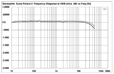
Fig.1 Sumo Polaris II, frequency response at 2.83V into 8 ohms (0.5dB/vertical div., right channel dashed).
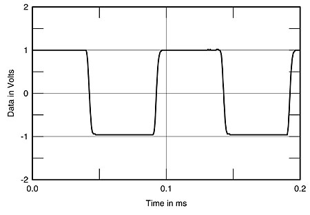
Fig.2 Sumo Polaris II, small-signal 10kHz squarewave into 8 ohms.
The sensitivity was significantly lower than the other three, it taking 138mV at 1kHz to give 1W output into an 8 ohm load, this equating to 26.2dB overall gain. Unweighted noise, too, was low at 76.2dB below 1W into 8 ohms, while DC offsets were a little high at –35mV/–75mV (L/R). Channel separation was excellent at better than 100dB below 600Hz, this worsening via capacitive coupling to 67dB at 20kHz.
Unlike the other three amplifiers, the Polaris's output impedances were typical of a solid-state design in being low. The right channel, for example, measured 0.09 ohms at 20Hz and 1kHz, rising to 0.11 ohms at 20kHz. The left channel was higher, however, at 0.15 ohms and 0.2 ohms at the same frequencies, which might suggest a problem.
My suspicions were confirmed when I measured the way in which distortion and noise changed with frequency (fig.3). From bottom to top at 100Hz, the traces represent THD and noise at 2.83V output: right channel into 8 ohms; right channel into 4 ohms; left channel into 8 ohms; left channel into 4 ohms; right channel into 2 ohms. While the right-channel figures are very low—much lower, for example, than any of the other amplifiers in this report—there is a significant rise in left-channel distortion with frequency, which could well correlate with the graininess CG noticed in the Sumo's sound (although the somewhat forward midrange balance, in my experience, could well have something to do with the amp's Mylar coupling caps).
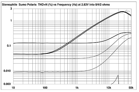
Fig.3 Sumo Polaris II, THD+N (%) vs frequency at 2.83V into (from bottom to top): 8 and 4 ohms, right channel; 8 and 4 ohms, left channel; 2 ohms, right channel.
The individual distortion waveforms of the right (fig.4) and left channels (fig.5) show why this should be so: While the right channel offers almost pure third harmonic with a bit of hum, the left channel features significant spikes at the sinewave zero-crossing points. It turned out that the distortion-trim control on the left channel didn't work—Sumo hand-trims the distortion-canceling circuitry of every Polaris before it leaves the factory—and had probably been damaged during the amplifier's travels around the US. (The review sample had been heavily used for demonstration purposes before we received it.) All subsequent measurements were performed on the right channel, this being assumed to be typical of production.
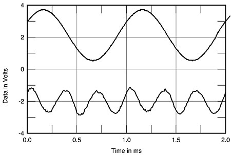
Fig.4 Sumo Polaris II, 1kHz waveform at 1W into 8 ohms, right channel (top), THD+N; distortion and noise waveform with fundamental notched out (bottom, not to scale).
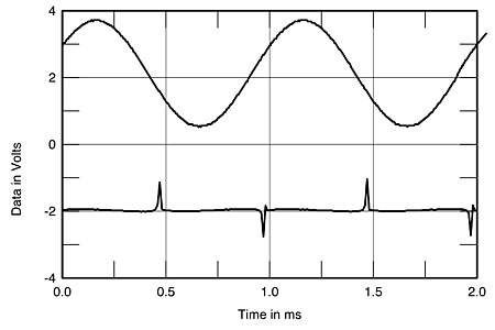
Fig.5 Sumo Polaris II, 1kHz waveform at 1W into 8 ohms, left channel (top), THD+N; distortion and noise waveform with fundamental notched out (bottom, not to scale).
Looking at the low-frequency distortion performance, fig.6 reveals this again to be primarily third-harmonic in nature—the cursor position reveals the 150Hz component to lie a good 56.3dB down from the fundamental—while the Polaris also did well on the high-frequency intermodulation test (fig.7), there being no appreciable LF components above the measurement system's 12-bit noise floor.
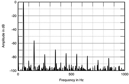
Fig.6 Sumo Polaris II, spectrum of 50Hz sinewave, DC–1kHz, at 72W into 4 ohms (linear frequency scale).

Fig.7 Sumo Polaris II, HF intermodulation spectrum, DC–24kHz, 19+20kHz at 48V peak–peak into 4 ohms (linear frequency scale).
With one channel driven, the maximum output power (1% THD) measured a hefty 145W (21.6dBW) into 8 ohms and 210W (20.2dBW) into 4 ohms, as shown by the plot of THD vs output power (fig.8). Unfortunately, I was unable to measure the 2 ohm clipping power as the right-channel ± voltage-rail fuses blew at 153W (the point where the 2 ohm trace stops in fig.8). After replacing the fuses, the channel's intrinsic distortion had risen by a factor of 10, suggesting that I had broken something and that further measurement would be unrepresentative.
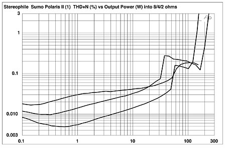
Fig.8 Sumo Polaris II, distortion (%) vs 1kHz continuous output power into (from bottom to top at 10W): 8, 4, and 2 ohms.
I find it interesting that the least expensive amplifier of this group measured the best (at least in one channel). As the original review sample turned out to be out of adjustment, we agreed that Sumo could submit a second sample. Corey described his reaction to its sound earlier; I managed to run a quick set of measurements before we sent it to Corey for auditioning.
While the output impedance of the two new channels was unchanged, the distortion signature was very different from the left channel of the first sample, as can be seen from fig.9, which plots THD+noise vs frequency at 2.83V into 8, 4, and 2 ohms. A comparison with fig.3 shows that the distortion-canceling circuitry drastically improves linearity below 1kHz. The rise in THD above that frequency to still inconsequential levels is apparently due to the fact that that canceling circuitry cannot be made to act too fast, otherwise it starts to chase its own tail. This change in distortion performance can also be seen in fig.10, which shows the spectrum up to 1kHz of a 50Hz tone at 65W into 4 ohms. Unlike fig.6, the only harmonics that can be seen above the measuring system's noise floor are the third at a minuscule –75dB (0.015%) and the fifth at an even lower level. And the two-tone intermodulation spectrum of the second sample (fig.11) shows only a slight accentuation of the 18 and 21kHz spurs, with no real 1kHz product present.
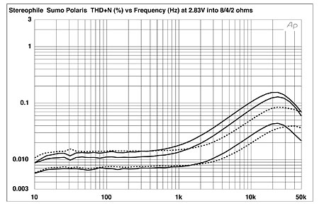
Fig.9 Sumo Polaris II, second sample, THD+N (%) vs frequency at 2.83V into (from bottom to top): 8, 4, and 2 ohms (right channel dashed).
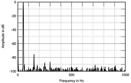
Fig.10 Sumo Polaris II, second sample, spectrum of 50Hz sinewave, DC–1kHz, at 70W into 4 ohms (linear frequency scale).
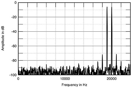
Fig.11 Sumo Polaris II, second sample, HF intermodulation spectrum, DC–24kHz, 19+20kHz at 48V peak–peak into 4 ohms (linear frequency scale).
Finally, the new sample's maximum output power was a little lower than the first's. With an AC line voltage of 115V rather than 116V, the 1% clipping points with one channel driven into 8 and 4 ohms were 124.7W (21dBW) and 195.5W (19.9dBW), respectively. These figures are shown graphically in fig.12, which plots THD+noise at 1kHz vs output power. (The incomplete trace is the 2 ohms delivery, the 4A rail fuses blowing at a hair over 200W into this load.) Note the very different manner in which THD increases with level compared with fig.8.
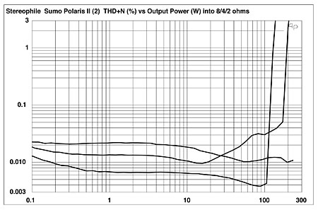
Fig.12 Sumo Polaris II, second sample, distortion (%) vs 1kHz continuous output power into (from bottom to top at 10W): 8, 4, and 2 ohms.
The reduced levels of distortion and the way those levels change with output power could well explain why CG felt the new sample to offer lower levels of grain. But as to why the second sample's lows were weaker in impact or why the stereo focus was poor, I have no idea.—John Atkinson
NEXT: Specifications »
|
| ||||||||||
- Log in or register to post comments


| Loudspeakers Amplification Digital Sources | Analog Sources Accessories Featured | Music Columns Retired Columns | Show Reports | Features Latest News Community | Resources Subscriptions |
 © 2024 Stereophile
AVTech Media Americas Inc., USA
All rights reserved

