| Columns Retired Columns & Blogs |
Seta Model L phono preamplifier Measurements
Sidebar 3: Measurements
Footnote 1: The bandwidth of the Seta L is deliberately rolled off internally at 5MHz, to avoid slew-rate limiting with active electronics downstream from the preamplifier.
I measured the Seta Model L with Stereophile's loan sample of the Audio Precision SYS2722 system (see the January 2008 "As We See It" and www.ap.com). I experimented with the grounding between the preamp and the analyzers to get the lowest level of noise. To fully charge the Model L's batteries, I left it plugged into the wall overnight. It ran off battery power for the measurements.
All the Model L preamplifier's inputs and outputs preserved absolute polarity; ie, were non-inverting. However, there was a problem with the right channel's Flat output. While the left channel's response (fig.1, blue trace) was fine, the output of the right channel started to rise above the audioband, reaching +10dB at 200kHz, which is the Audio Precision's upper frequency limit. I checked the positions of all the jumpers I could see on the circuit board, but could see nothing amiss. I cycled the front-panel gain button several times after connecting the power supply to get both channels into the same state, without any effect on the right channel's behavior. Thinking it might be a cable problem, I swapped leads and analyzer channels—if so, the ultrasonic boost would then have moved to the other channel—but it was still the right channel that was affected.
I opened Channel D—the company must have gotten its name from The Man from U.N.C.L.E., right?—and Robert Robinson sent me a second sample for measurement. Unfortunately, the only sample available to send me was the earlier two-box version of the Model L, whose RIAA circuitry is housed in a separate enclosure. I comment in the text where this is different from the correctly performing channel of the single-box version.
The cyan and magenta traces in fig.1 show the frequency response of the new sample's Flat balanced output. It is perfectly flat, with excellent channel balance up to 200kHz, whereas the original sample has a –0.7dB shelf above 1kHz. According to Robinson, this was a design trade-off for the internal RIAA module in the single-box version. This module's use of passive rather than active correction of the high-frequency RIAA time constant causes a slight loading of the input stage.
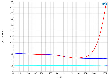
Fig.1 Channel D Seta Model L, Flat output responses of first sample (left channel blue, right red) and second sample (left cyan, right magenta; offset for clarity). (1dB/vertical div.)
Because an amplifier will be used in many different and unknown circumstances, I have always believed in rolling off a circuit's output somewhere above its nominal passband. I therefore asked Robinson about the wisdom of designing a phono preamplifier to have such a wide bandwidth (footnote 1). He responded that, rather than attempt to filter out-of-band signals, it was better to accommodate them. "A nice benefit to a wide-bandwidth design is that any deleterious effects that are associated with the use of negative feedback (eg, there is some feedback in the input stage) are moved to well above the audio frequency range. The signal delay of the input stage is just a few nanoseconds—orders of magnitude faster than an audio signal—and so the feedback operates much, much faster than in a conventional audio amplifier. Finally, the fast-rising waveform of vinyl pops and clicks is unlike any musical waveform. A wide-bandwidth, fast preamplifier will track these features; a filtered input will stretch them, and a slow-responding input stage may go into slew-rate limiting. Either of those situations will accentuate their audibility. The only downside to this approach (other than being tricky to implement), all else being equal, is somewhat higher noise; but when the stylus is placed in the groove, that higher noise level is overwhelmed by the vinyl background [noise]."
The red and blue traces in fig.2 show the response of the original sample's internal RIAA module. The channels are superbly matched and the response is beautifully flat above 1kHz. There is a slow rise in output with decreasing frequency, reaching +0.6dB at 20Hz, which may be just audible. The green and gray traces in this graph show the response with the infrasonic filter switched in-circuit with the internal jumpers; the output is down by 3dB at 10Hz, as specified. The cyan and magenta traces in fig.2 show the response of the second sample's external RIAA module—while the response error is very low and, again, the channels are well matched, it is different in shape from the first sample's response, with a rolloff above 52kHz. The external module also doesn't have a 10Hz subsonic filter.
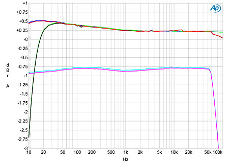
Fig.2 Channel D Seta Model L, balanced RIAA output responses of first sample with (left channel green, right gray) and without (left blue, right red) 10Hz low-cut filter; and of second sample (left cyan, right magenta; offset for clarity). (1dB/vertical div.)
The output impedances of both samples were close to specification, at 40 ohms balanced and 20 ohms unbalanced for the first sample, and 36 ohms balanced and 18 ohms unbalanced for the second sample. The first sample of the Model L had rotary switches on the rear panel to set input impedance; the second sample used different-value resistors plugged into internal sockets. Both samples offered accurate matching of the measured input impedance to the nominal values, but with a slight error that increased as the nominal value increased. The first sample's balanced input impedance was 51 ohms at "50," 103 ohms at "100," 156 ohms at "150," 209 ohms at "200," 580 ohms at "500," and 1330 ohms at "1k." The unbalanced input impedance was 103 ohms at "100" and 998 ohms at "1k." The second sample of the Model L had only balanced inputs; the input impedance was 182 ohms at "200," 662 ohms at "1000," and 1966 ohms with no loading resistors inserted. None of these differences will have any subjective consequences.
Both samples offer a choice of four voltage gains, but differed a little in the details. The first, one-box sample offered gains of 41.2, 46.2, 50.8, and 56.56dB from its Flat balanced outputs. The gain from its balanced RIAA output was not significantly affected by the Flat gain setting, at 54–55dB; by contrast, the second, two-box sample's gain from the RIAA outputs followed the Flat gain setting, at 54.2, 57.1, 59.9, and 67.7dB. The Flat outputs offered 42.2, 45, 47.9, and 51.7dB. The choices of gain will allow the Seta L to be optimally matched to any soundcard.
Channel separation was excellent for both samples, at 90dB in both directions for the RIAA-equalized outputs and 100dB below 500Hz for the Flat outputs, decreasing at 20kHz to 79dB L–R and 85dB R–L. The wideband signal/noise ratios—with the maximum gain setting, the input shorted to ground, and ref. the nominal MC cartridge level of 500µV for a recorded velocity of 5cm/s at 1kHz —were similar for both samples of the Model L, at 55dB RIAA and 45dB Flat. Restricting the measurement bandwidth to the audioband improved both these ratios to 59dB, while A-weighting the measurements gave 67dB RIAA and 61.5dB Flat, which is good.
Fig.3 shows how the THD+noise percentage in the Seta L's Flat balanced output varied with output voltage. The downward slope of the traces with increasing voltage indicates that any distortion is buried under the noise up to the point where the waveform starts to clip. This is obviously a very linear circuit. The actual clipping points (defined as 1% THD) are 8.6V RMS into 10k ohms and 7.5V into 600 ohms, both well above what will be required in practical use. The former is equivalent to an overload margin of 26.8dB ref. an input at 500µV at 1kHz, and still more than 6dB at 20kHz, even if there were full-scale musical energy cut on the LP at that frequency (which there never is). From the RIAA-equalized outputs, the overload margins were a good 21.4dB at low and middle frequencies, dropping slightly to 15dB at 20kHz.
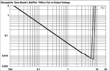
Fig.3 Channel D Seta Model L, balanced Flat output, distortion (%) vs 1kHz output level into (from bottom to top at 8V): 100k, 600 ohms.
A very linear circuit? Fig.4 shows the spectrum of the Seta L's balanced RIAA-equalized output at 2V into 100k ohms. The sloped-down noise floor is due to the RIAA deemphasis, but no distortion harmonics can be seen above the noise floor, even when the load impedance is reduced to a punishing 600 ohms! Some low-frequency spikes can be seen in the right channel's output (red trace). I thought at first that these were harmonically related to the 60Hz frequency of the wall AC power—until I remembered that the Seta L was running off its batteries. However, it appeared that these low-level spikes in the right channel had frequencies of 80, 200, 240, and 360Hz, so I have no idea from where they arise. These spikes can also be seen in fig.5, which shows a similar analysis for the Flat output into 600 ohms. Without the shaping of the noise floor, a trace of second harmonic can now be seen, but at –106dB (0.0005%), this is not going to bother anyone.
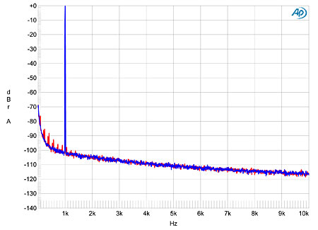
Fig.4 Channel D Seta Model L, balanced RIAA output, spectrum of 1kHz sinewave, DC–10kHz, at 2V into 100k ohms (left channel blue, right red; linear frequency scale).
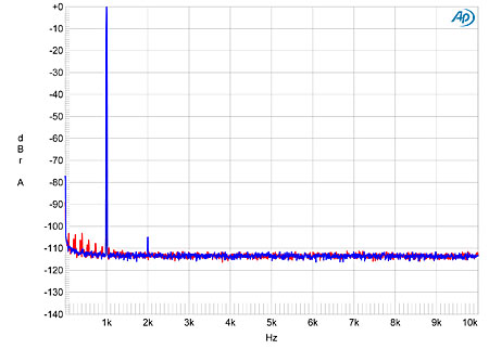
Fig.5 Channel D Seta Model L, balanced Flat output, spectrum of 1kHz sinewave, DC–10kHz, at 2V into 600 ohms (left channel blue, right red; linear frequency scale).
Finally, fig.6 shows the spectrum of the Seta L's Flat output while it drove an equal mix of 19 and 20kHz tones into 100k ohms. No intermodulation products can be seen! However, a low-level tone is visible in the left channel at 20,500Hz. Again, I have no idea where this comes from, as it is not mathematically related to the fundamental tones or their harmonics.
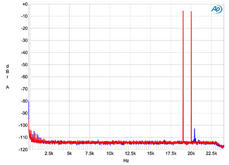
Fig.6 Channel D Seta Model L, balanced Flat output, HF intermodulation spectrum, DC–24kHz, 19+20kHz at 2V peak into 100k ohms (linear frequency scale; left channel blue, right red).
It took me a while to get my head around the Seta Model L's measured performance, because I had to keep reminding myself of what were typical recorded levels on LPs before the cartridge's output had been equalized by the RIAA characteristic. But there is no doubt that the Seta Model L—whether the single-box version auditioned by MF or the two-box model on which I performed most of my measurements—has been superbly engineered. It's not the quietest phono preamplifier I have measured, but, as Channel D's Robert Robinson points out, its own noise will still be lower than the groove noise of a typical LP. There is the issue of the original sample's right channel, but that may well be due to something having gone awry in shipping. This was a well-traveled unit.—John Atkinson
Footnote 1: The bandwidth of the Seta L is deliberately rolled off internally at 5MHz, to avoid slew-rate limiting with active electronics downstream from the preamplifier.
NEXT: John Atkinson, December 2013 »
|
|
| ||||||||||
- Log in or register to post comments


| Loudspeakers Amplification Digital Sources | Analog Sources Accessories Featured | Music Columns Retired Columns | Show Reports | Features Latest News Community | Resources Subscriptions |
 © 2024 Stereophile
AVTech Media Americas Inc., USA
All rights reserved

