SAE 2HP-D power amplifier Measurements

Sidebar 3: Measurements

I performed a full set of measurements on the SAE 2HP-D, using my Audio Precision SYS2722 system (see the January 2008 "As We See It"). Usually, before doing any testing of a power amplifier, I precondition it by running it at one-third power into 8 ohms for an hour. (With an amplifier having a class-B or -AB output stage, this power level results in the highest thermal stress on the output devices.) However, the 2HP-D is a very powerful amplifier, and I don't have a test load that could handle both channels running at 250W for an hour without overheating. So I wasn't able to precondition the SAE before testing it. However, I did leave it running at a lower power for an hour or so; at the end of that time, its heatsinks were too hot to touch, at 141.4°F (60.8°C), and its top panel was also hot, at 93.2°F (34°C). A switch on the 2HP-D's rear panel activates a cooling fan; when I continued the testing with this fan switched on, the heatsink temperature never rose above 134.6°F (57°C). Even so, this is an amplifier that will need plenty of ventilation.

The 2HP-D's voltage gain into 8 ohms measured 27.7dB, an input signal of 1kHz at 100mV resulting in an output of 2.424V into 8 ohms, which the front-panel display indicated as 0.74W RMS, 1.64W peak, and –29dB. The amplifier preserved absolute polarity (ie, was non-inverting). Its balanced input impedance is specified as 94k ohms (47k ohms per each phase). My estimates were a little lower than this, at 61k ohms at 20Hz, 64k ohms at 1kHz, and 53k ohms at 20kHz, but these differences are inconsequential.

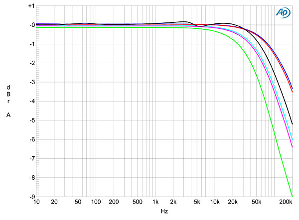
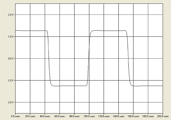
The output impedance, including 6' of cable, was very low at low and middle frequencies, at 0.08 ohm, but the impedance did rise to 0.25 ohm at the top of the audioband. As a result, while the modification of the 2HP-D's frequency response by the interaction between its source impedance and that of our standard simulated loudspeaker was very small (fig.1, gray trace), and its response into 8 ohms (blue, red) was flat up to 20kHz, its responses into 4 ohms (cyan, magenta) and 2 ohms (green) at 20kHz were respectively rolled off by 0.3 and 0.7dB. The 2HP-D still had a wide frequency response, extending to –3dB at 180kHz into 8 ohms, and its reproduction of a 10kHz squarewave was essentially perfect, with no overshoot or ringing (fig.2).

1016sae.SAEfig01.jpg

Fig.1 SAE 2HP-D, frequency response at 2.83V into: simulated loudspeaker load (gray), 8 ohms (left channel blue, right red), 4 ohms (left cyan, right magenta), 2 ohms (green) (0.5dB/vertical div.).

1016sae.SAEfig02.jpg

Fig.2 SAE 2HP-D, small-signal, 10kHz squarewave into 8 ohms.

With its dual-mono construction, it was not surprising to find that the 2HP-D's channel separation was superb, at 110dB or better in both directions below 3kHz. The wideband, unweighted signal/noise ratio (ref.2.83V into 8 ohms and measured with the input shorted to ground) in the left channel was a little disappointing, at 79.1dB; the right-channel ratio was better, at 83.5dB. Restricting the measurement bandwidth to the audioband improved the ratios to 81.6 and 85.9dB, respectively, while switching in an A-weighting filter gave further improvement, to 85.2 and 89.1dB. Given the 2HP-D's very high maximum output voltage—1hp is equivalent to 746W into 8 ohms, in turn equivalent to an RMS voltage of 77.25V!—the right channel's A-weighted ratio of 89.1dB ref. 1W into 8 ohms is equivalent to 117.8dB ref. the specified full power. This is excellent, if lower than the specified figure of 128dB.

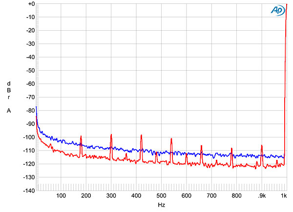
Spectral analysis of the 2HP-D's low-frequency noise floor while it reproduced a 1kHz tone into 8 ohms (fig.3) indicated that the left channel's smaller, unweighted ratio was due to a higher level of random noise (blue trace). By contrast, the right channel's noise floor featured spuriae at the odd-order harmonics of the 60Hz AC mains frequency. Odd harmonics are most likely due to magnetic interference from the power-supply transformer. Though these all lay at or below –100dB, their presence explains the difference between my measured S/N ratio and SAE's specification.

1016sae.SAEfig03.jpg

Fig.3 SAE 2HP-D, spectrum of 1kHz sinewave, DC–1kHz, at 1W into 8 ohms (left channel blue, right red; linear frequency scale).

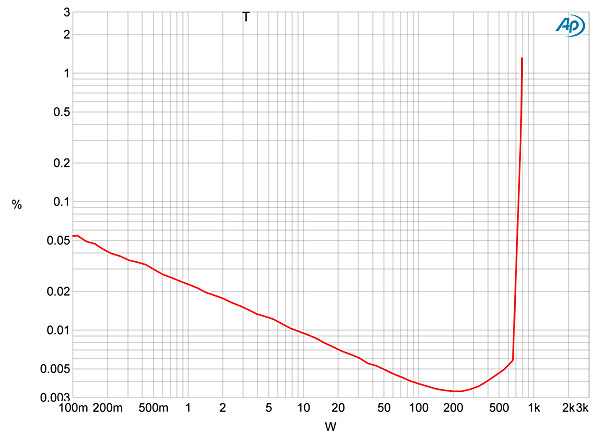
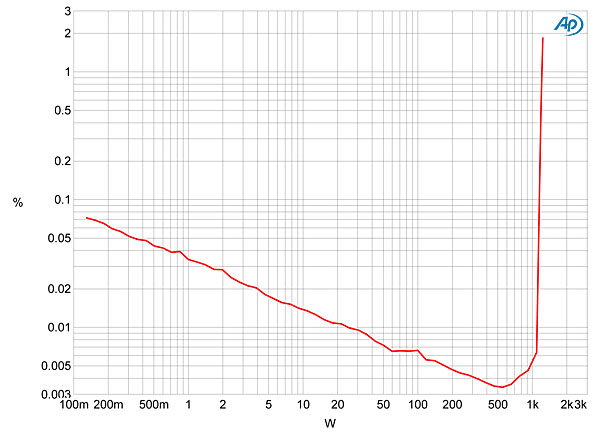
Fig.4 plots the percentage of THD+noise in the left channel against power into 8 ohms (both channels were driven for this test). The downward slope of the trace up to 200W means that actual distortion is below the noise floor. (A constant level of noise becomes an increasingly smaller percentage of power as the latter increases.) The distortion at 200W is extremely low, at 0.0033%, and the 2HP-D clips (defined as 1% THD+N) at no less than 780Wpc into 8 ohms (28.9dBW). This is 0.2dB higher than 1hp, and would have been even more had I held the wall voltage at 120V. (The AC voltage measured 119.8V with the 2HP-D outputting 1Wpc into 8 ohms; this dropped to 113.9V with both channels clipping into 8 ohms.) Into 4 ohms with both channels driven (fig.5), the left channel clipped at 1210W (27.8dBW) with the AC voltage at clipping 109.5V, while with just the left channel driven into 2 ohms, the amplifier clipped at 2kW (27.0dBW). Wow!

1016sae.SAEfig04.jpg

Fig.4 SAE 2HP-D, both channels driven, distortion (%) vs 1kHz continuous output power into 8 ohms.

1016sae.SAEfig05.jpg

Fig.5 SAE 2HP-D, both channels driven, distortion (%) vs 1kHz continuous output power into 4 ohms.

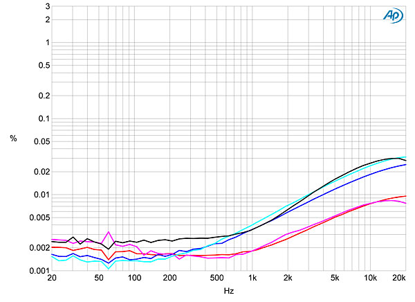
The clipping measurements were taken from the left channel's output, but when I plotted how the two channels' THD+N percentage varied with frequency at a level, 31V, where I was looking at distortion rather than noise, it appeared that the left channel (fig.6, blue, cyan, and gray traces) was slightly less linear than the right (red, magenta). The THD+N increased in the treble in both channels, presumably due to the circuit's gain-bandwidth product decreasing at high frequencies, thus reducing the amount of corrective negative feedback available, though not to a significant degree. But at 1kHz, the THD+N measured above 0.003% in the left channel, and was almost half that amount in the right channel. I swapped the loads and speaker cables for different ones—in light of MF's experience with different AC cables, I tried different ones—but the left channel's THD+N percentage remained higher than the right's despite all the changes.

1016sae.SAEfig06.jpg

Fig.6 SAE 2HP-D, THD+N (%) vs frequency at 31V into: 8 ohms (left channel blue, right red), 4 ohms (left cyan, right magenta), 2 ohms (left gray).

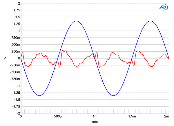
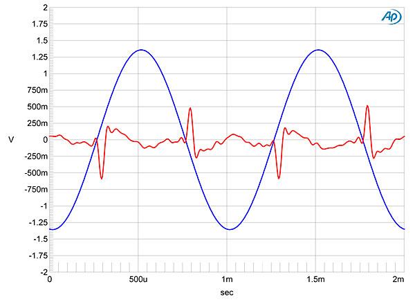
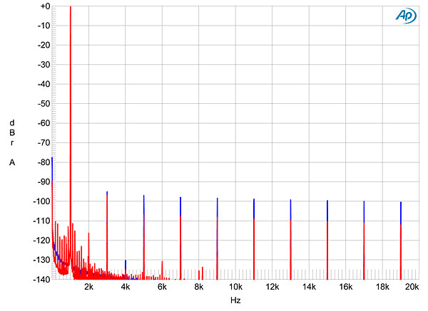
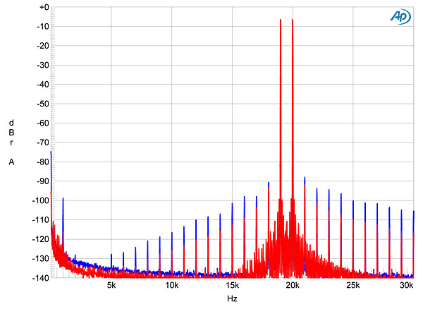
I examined this difference between the channels more closely by looking at the waveform of the residual THD+N. Fig.7 shows the right channel's behavior at the same power into 8 ohms that I used to generate fig.6. The distortion waveform is primarily third harmonic in nature, and the level is just 0.0019%. By contrast, fig.8 shows the left channel's behavior. The level of the distortion has risen to 0.0031%, and as well as some third-harmonic content, spikes are visible at the signal's zero-crossing points. It looks as if, somewhere in the left channel's circuit, there is insufficient bias current. Though the distortion signature in both channels is primarily third harmonic, greater amounts of higher-order harmonics are present in the left (fig.9). When I tested the 2HP-D's intermodulation behavior with an equal mix of 19 and 20kHz tones, the combined waveform peaking at 240Wpc into 4 ohms, the left channel (fig.10, blue trace) was again less linear than the right (red), the 1kHz difference product lying at –116dB (0.00015%) in the right channel but at –99dB (0.0011%) in the left.

1016sae.SAEfig07.jpg

Fig.7 SAE 2HP-D, right channel, 1kHz waveform at 120W into 8 ohms, 0.0019% THD+N (blue); distortion and noise waveform with fundamental notched out (red, not to scale).

1016sae.SAEfig08.jpg

Fig.8 SAE 2HP-D, left channel, 1kHz waveform at 120W into 8 ohms, 0.0031% THD+N (blue); distortion and noise waveform with fundamental notched out (red, not to scale).

1016sae.SAEfig09.jpg

Fig.9 SAE 2HP-D, spectrum of 1kHz sinewave, DC–20kHz, at 120W into 8 ohms (left channel blue, right red, linear frequency scale).

1016sae.SAEfig10.jpg

Fig.10 SAE 2HP-D, HF intermodulation spectrum, DC–24kHz, 19+20kHz at 240W peak into 4 ohms (left channel blue, right red, linear frequency scale).

In almost all respects, SAE's 2HP-D is an extraordinary amplifier. It offers very high output power with extremely low levels of both harmonic and intermodulation distortion, even in the less-good left channel. If it weren't for the left channel's behavior, which may have been due to a manufacturing fault or a problem that developed after the amplifier had been in use (footnote 1), I would have nothing negative to say about the 2HP-D's measured performance.—John Atkinson


Footnote 1: It turned out that this sample of the SAE's 2HP-D was much traveled, having been used at the 2016 CES before ending up in MF's system. It is possible, therefore, that something had gone adrift in the multiple instances of shipping. I have been promised a new sample and will repeat the signal/noise ratio and distortion measurements in a follow-up review.—John Atkinson
COMPANY INFO
SAE (Scientific Audio Electronics)
1749 Chapin Road
Montebello, CA 90640
844-4HEARSAE
ARTICLE CONTENTS

COMMENTS
Anon2's picture

I enjoyed this review on a variety of fronts. I am glad to see SAE back on the scene. I had an SAE tape deck back in the day, before abandoning cassettes for my first Kyocera CD player.

I hope that SAE comes out with some more products.

This review was also a walk down memory lane of California entrepreneurship from the 1980s. The story of rise, fall, and rising again (in the 1980s, 1990s, and today) provided lessons going far beyond the audio hobby. It's good to see a legacy California business bringing back brands once left for dead. It's even better to hear of an existing electronics manufacturer in the US, standing in the shadow of downtown/East LA and Dodger Stadium.

It's "To Die and Live (Again) in LA" with this great historical essay on SAE, Southern California industrial resourcefulness, a comeback that none expected, and a repurposed and retooled operation that was in the background but never really went away.

As an epilogue to this story, Tokai bank itself was swallowed up in a merger with Sanwa Bank (I remember the Sanwa Bank tower in downtown LA). Later these components all fell into the current Bank of Tokyo/Mitsubishi UFJ conglomerate.

It's another great testament that SAE, in light of all of this, now comes back as an independent brand, still tethered to its original founders, while the one-time creditor has now been absorbed through a series of mergers back home.
georgehifi's picture

These sort of arc welders are good for speakers like Wilson Alexia, which with the their negative phase angle plus load can represent a combined load of .9ohm

Cheers George

X