| Columns Retired Columns & Blogs |
Roksan Kandy K2 integrated amplifier Measurements
Sidebar 3: Measurements
I examined the Roksan Kandy K2's measured behavior using mainly Stereophile's loan sample of the top-of-the-line Audio Precision SYS2722 system (see the January 2008 "As We See It" and www.ap.com); for some tests, I also used my vintage Audio Precision System One Dual Domain.
Before I test an amplifier, I run it for 60 minutes at one-third its specified power into 8 ohms. Thermally, this worst case for an amplifier with a class-B or -AB output stage taxes its heatsinks' ability to dissipate waste heat. The Kandy K2's top panel got too hot to touch after just 20 minutes; as I could smell hot insulation after 30 minutes, I stopped the preconditioning at that point. The Roksan doesn't have quite enough heatsink area for an amplifier of this power rating; however, that will be unlikely to prove a problem under normal conditions.
Looking first at the moving-magnet phono stage, this offered 40dB of gain and preserved absolute polarity. Its input impedance was rather lower than the specified 47k ohms, at 16.4k ohms. The departure from RIAA equalization is shown in fig.1; though the error is low in absolute terms, the slight boost in the lower midrange and the slight tilt up in the top two octaves might be just audible because of the wide range covered. The two channels are well matched, other than the small difference centered on 200Hz. The phono stage's wideband, unweighted signal/noise ratio, ref. 1kHz at 5mV input, was good, at 59.8dB left and 61.6dB right, these figures improving to 76.6dB and 76.8dB, respectively, when A-weighted. The phono stage offered low distortion, typically 0.015%, with good overload margins ranging from 21.6dB at 20Hz to 19.8dB at 20kHz.
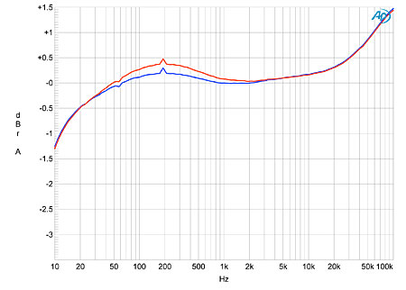
Fig.1 Roksan Kandy K2, RIAA error of MM phono input (left channel blue, right red; 0.25dB/vertical div.).
Turning to the line inputs, the maximum gain measured at the preamplifier outputs was as specified, 5.67dB, with the power-amplifier section offering an additional 31.23dB gain (measured into 8 ohms). The line input impedance was also lower than specified, at 23k ohms at low and middle frequencies, dropping slightly to 19.5k ohms at 20kHz. The preamplifier outputs offered a low source impedance of 128 ohms over most of the audioband, rising at 20Hz to a still low 150 ohms. The preamp output, headphone output, and the speaker output all preserved absolute polarity.
The power-amplifier section's output impedance was a very low 0.09 ohm at low and middle frequencies, rising slightly to 0.15 ohm at 20kHz due to the usual series Zobel inductor. The modulation of the amplifier's frequency response by the interaction between this output impedance and the impedance of the loudspeaker was therefore small, at ±0.1dB (fig.2, gray trace). The Kandy K2 has a wide small-signal bandwidth, not reaching –3dB into 8 ohms until 96kHz (fig.2, blue and red traces), and the channel matching can be seen from this graph to be excellent. However, this graph was taken with the volume control at its maximum; at settings more typical of normal use (fig.3), the left channel was more than 1dB higher in level than the right, which cannot be corrected with the balance control—there doesn't appear to be one.
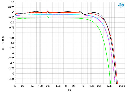
Fig.2 Roksan Kandy K2, volume control at maximum, frequency response at 2.83V into: simulated loudspeaker load (gray), 8 ohms (left channel blue, right red), 4 ohms (left cyan, right magenta), 2 ohms (green). (0.25dB/vertical div.)
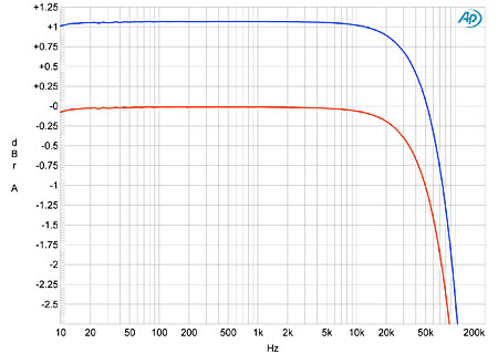
Fig.3 Roksan Kandy K2, volume control at 12:00, frequency response at 2.83V into 8 ohms (left channel blue, right red; 0.25dB/vertical div.).
With its wide bandwidth, the K2 gives very good squarewave reproduction (fig.4). Channel separation at 1kHz was good rather than great, at 80dB L–R and 88dB R–L. These figures worsened slightly at the top of the audioband, to 60dB and 75dB, respectively. S/N ratios were also good rather than great. Taken with the input shorted but the volume control at its maximum, the unweighted, wideband figures were 65.2dB left but 51.3dB right. With A-weighting, these ratios improved to 76.6dB and 74.6dB, respectively.
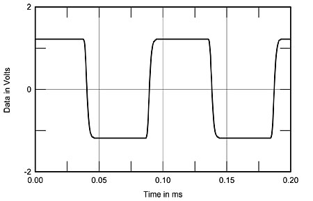
Fig.4 Roksan Kandy K2, small-signal 10kHz squarewave into 8 ohms.
The Kandy K2 comfortably exceeded its specified output power into 8 ohms, clipping (defined as 1% THD+noise) at 137Wpc with both channels driven (21.37dBW). Into 4 ohms, it clipped at 199Wpc (20dBW). Fig.5 shows how the THD+N varied with output power from the quieter left channel; it is respectably low at all powers below clipping. I measured how the THD+N percentage varied with frequency at a medium level, 9V, equivalent to 10W into 8 ohms. The right-channel readings into 8 and 4 ohms (fig.6, red and magenta traces) are dominated by noise, but common factors for both channels in this graph are the rise in THD at low frequencies into all loads and at high frequencies into 2 ohms (green and gray traces).
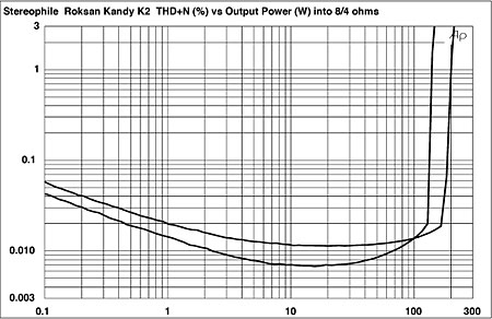
Fig.5 Roksan Kandy K2, distortion (%) vs 1kHz continuous output power into (from bottom to top below 10W): 8, 4 ohms.
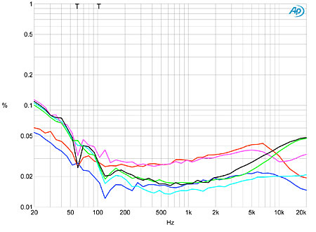
Fig.6 Roksan Kandy K2, THD+N (%) vs frequency at 9V into: 8 ohms (left channel blue, right red), 4 ohms (left cyan, right magenta), 2 ohms (left green, right gray).
At low powers the distortion is predominantly the subjectively harmless second harmonic (fig.7), but at higher powers this is joined by a regular series of higher-order harmonics (fig.8). The 120Hz power-supply component lies at –80dB (0.01%) in the right channel in this graph, and lower-level spuriae are also at 60Hz, 180Hz, and 300Hz. The levels of these supply-related components were affected by the grounding used during the testing. This graph was taken with the input ground floating and the AC ground disconnected, which gave the lowest level of spuriae, but the amplifier was not unconditionally stable in this condition, its protection cutting in at higher levels. And while the actual intermodulation products with the high-power, high-frequency, two-tone test are quite low—the 1kHz difference product in fig.9 lies at –80dB (0.01%)—the noise floor is shaped by the presence of power-supply–related spuriae. (The input and AC grounds were connected during this test.) Also visible in this graph are pairs of supply-related sidebands at 19kHz, ±120Hz and 20kHz, ±120Hz—the K2 is obviously working hard.
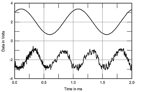
Fig.7 Roksan Kandy K2, 1kHz waveform at 4.8W into 4 ohms (top), 0.01% THD+N; distortion and noise waveform with fundamental notched out (bottom, not to scale).
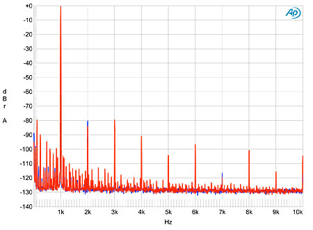
Fig.8 Roksan Kandy K2, spectrum of 1kHz sinewave, DC–10kHz, at 136.7W into 4 ohms (left channel blue, right red; linear frequency scale).
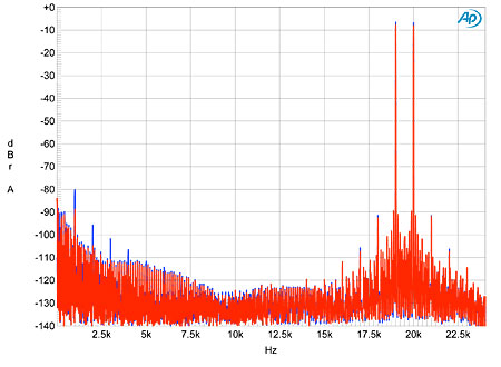
Fig.9 Roksan Kandy K2, HF intermodulation spectrum, DC–24kHz, 19+20kHz at 106W peak into 4 ohms (linear frequency scale).
Roksan's Kandy K2 offers high power with quite respectable measured performance at a relatively affordable price, but I was bothered by the higher level of noise in the right channel and the poor volume-control tracking.—John Atkinson
|
| ||||||||||
- Log in or register to post comments


| Loudspeakers Amplification Digital Sources | Analog Sources Accessories Featured | Music Columns Retired Columns | Show Reports | Features Latest News Community | Resources Subscriptions |
 © 2024 Stereophile
AVTech Media Americas Inc., USA
All rights reserved

