| Columns Retired Columns & Blogs |
Rogue Audio Atlas power amplifier Measurements
Sidebar 3: Measurements
Footnote 1: A reader recently asked why my squarewave graphs are free from the ringing on transitions that is usual with digital oscilloscopes. I use an antique (ca 1987) Heathkit 'scope that lacks an antialiasing filter. Provided this 'scope is used with a high enough sampling frequency, it captures accurate squarewave responses.—John Atkinson
Before performing any measurements on the Rogue Audio Atlas, I checked the bias of its four KT77 output tubes. All were running at around 40mA bias current, close to the 35mA recommended by the manufacturer. I tested the Atlas with its output transformer hooked up for 8 ohm operation, as usually supplied by Rogue, and also as wired for 4 ohm operation, as ultimately used by Fred Kaplan in his auditioning. To my surprise, the voltage gain into 8 ohms was the same from both output-transformer windings—26.5dB—despite the 8 ohm tap's greater intrinsic gain. This is presumably due to the extra amplification being compensated for by the associated increase in output impedance. Both taps preserved absolute polarity; ie, were noninverting. The amplifier's input impedance was extremely high, at around a megohm at low and midrange frequencies, dropping to around 500k ohms at 20kHz. (It is difficult to accurately measure such high AC impedances.) The Atlas will not load the partnering preamplifier at all.
The Atlas' output impedance from the 4 ohm tap was relatively low for a tubed design, at 0.34 ohm at 1kHz, rising to 0.65 ohm at 20Hz and 0.8 ohm at 20kHz. These impedances increased slightly from the 8 ohm tap—to 0.9, 0.47, and 1.1 ohm, respectively—resulting in moderate ±0.4dB variations in the amplifier's frequency response with our standard simulated loudspeaker (fig.1, top trace at 80Hz and 2kHz). However, the increase in output impedance at the frequency extremes resulted in a slight, 0.6dB rolloff at these frequencies and a correspondingly greater rolloff into lower impedances. In the worst case—the 8 ohm tap driving 2 ohms (fig.1, bottom trace)—the Atlas' output was down 3dB at 20kHz. Even so, a 1kHz squarewave was reproduced with short risetimes and flat tops (fig.2). The 10kHz squarewave, however, showed a small amount of ultrasonic ringing (fig.3), suggesting the presence of a parasitic resonance somewhere in the circuit (footnote 1).
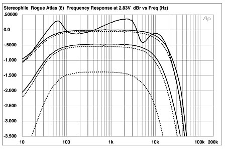
Fig.1 Rogue Audio Atlas, 8 ohm tap, frequency response at 2.83V into (from top to bottom at 2kHz): simulated loudspeaker load, 8, 4, 2 ohms (0.5dB/vertical div., right channel dashed).
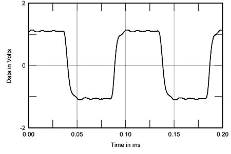
Fig.2 Rogue Audio Atlas, 4 ohm tap, small-signal 1kHz squarewave into 8 ohms.
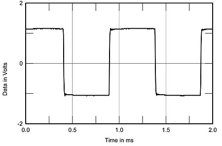
Fig.3 Rogue Audio Atlas, 4 ohm tap, small-signal 10kHz squarewave into 8 ohms.
Channel separation (not shown) was good at better than 90dB at 1kHz, but decreased to 75dB at 20kHz. The Rogue's signal/noise ratios were dominated by a small amount of 60Hz hum that I couldn't eliminate no matter how I arranged the grounding between the amplifier and my Audio Precision System One test set. There was also a small amount of ultrasonic ringing evident. The wideband, unweighted S/N figure (ref. 2.83V into 8 ohms) was thus 59dB, improving as expected to 79.3dB when A-weighted. If the Atlas is used with high-sensitivity speakers, the hum might be just audible.
The Atlas handily exceeded its specified power of 55W (17.4dBW) from both taps. With the load impedance matching the nominal transformer tap and one channel driven, I measured power at clipping (1% THD+noise) as 101W (17dBW) from the 4 ohm tap and 100W (20dBW) from the 8 ohm tap—good going for a pair of KT77s/EL34s. As expected, with both channels driven, the 8 ohm tap delivered a little less power—86W (19.35dBW)—but this is still significantly higher than specified. Almost as much power was delivered into loads of half the nominal tap value, but, as shown by the graphs of distortion vs output power (fig.4, 4 ohm tap; fig.5, 8 ohm tap), the Atlas is clearly uncomfortable driving impedances that are less than this.
Figs.4 and 5 also show that the Rogue's THD+N is dominated by noise below about 10W, at least into the higher impedances. I therefore plotted how the THD+N percentage changed with frequency at a level of 9V, equivalent to 10W into 8 ohms. Fig.6 shows the behavior from the 4 ohm tap; the 8 ohm tap (fig.7) is broadly similar, though with distortion levels slightly higher. Though the THD from the upper bass through the mid-treble is low into high impedances for a tube design, at less than 0.05%, it does rise significantly once the load is the same as the nominal transformer tap and at high frequencies. Even the 4 ohm tap is producing potentially audible distortion into 2 ohms, even below 2.5kHz. The Atlas' circuit clearly has insufficient open-loop bandwidth for negative feedback to be sufficiently effective with combinations of high frequencies and high output currents.
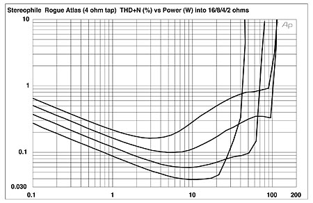
Fig.4 Rogue Audio Atlas, 4 ohm tap, distortion (%) vs 1kHz continuous output power into (from bottom to top at 10W): 16, 8, 4, 2 ohms, one channel driven.
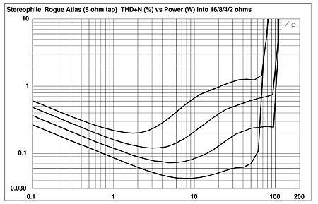
Fig.5 Rogue Audio Atlas, 8 ohm tap, distortion (%) vs 1kHz continuous output power into (from bottom to top at 10W): 16, 8, 4, 2 ohms, one channel driven.
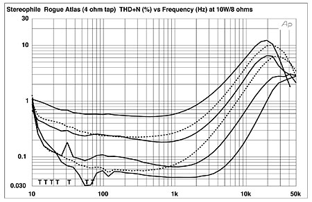
Fig.6 Rogue Audio Atlas, 4 ohm tap, THD+N (%) vs frequency at 9V into (from bottom to top): 16, 8, 4, 2 ohms (right channel dashed).
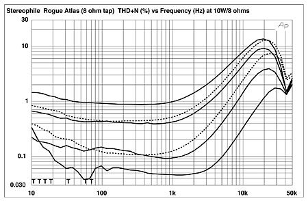
Fig.7 Rogue Audio Atlas, 8 ohm tap, THD+N (%) vs frequency at 9V into (from bottom to top): 16, 8, 4, 2 ohms (right channel dashed).
Fortunately, the distortion content is predominantly the more subjectively benign low-order harmonics. Fig.8 also shows a trace of the low-level ultrasonic ringing that has not been eliminated by the usual oscilloscope trace averaging. (To better reveal the harmonic content, I average 32 captures to reduce the amount of asynchronous noise in the graph.) However, at higher powers and at low frequencies, the Atlas does produce a regular series of higher-order harmonics (fig.9). The second harmonic is still the highest in level in this graph, at –55dB (0.16%), though the third harmonic starts to dominate at higher currents (fig.10), presumably due to the output transformer beginning to saturate.
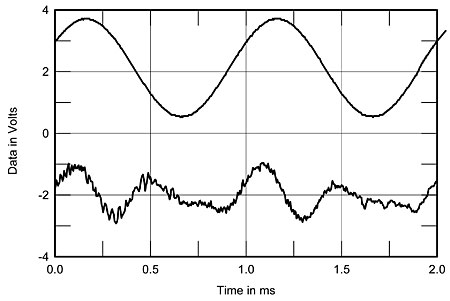
Fig.8 Rogue Audio Atlas, 4 ohm tap, 1kHz waveform at 4.1W into 4 ohms (top), 0.104% THD+N; distortion and noise waveform with fundamental notched out (bottom, not to scale).
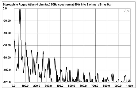
Fig.9 Rogue Audio Atlas, 4 ohm tap, spectrum of 50Hz sinewave, DC–1kHz, at 50W into 8 ohms (linear frequency scale).
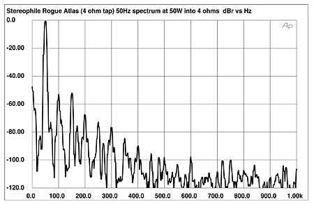
Fig.10 Rogue Audio Atlas, 4 ohm tap, spectrum of 50Hz sinewave, DC–1kHz, at 50W into 4 ohms (linear frequency scale).
The decreasing linearity of the Rogue Atlas' circuit at high frequencies causes the amplifier to stumble on the high-frequency intermodulation test. Admittedly, an amplifier unlikely to ever encounter a combination of 19kHz and 20kHz tones at a level just below clipping, but the slews of intermodulation products and power-supply–related sidebands (fig.11) indicate that this is the Rogue's Achilles' heel, and probably the root cause of the "steeliness" noted by FK.
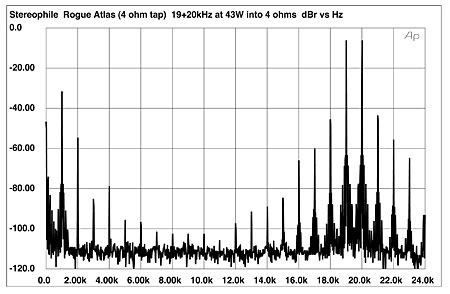
Fig.11 Rogue Audio Atlas, 4 ohm tap, HF intermodulation spectrum, DC–24kHz, 19+20kHz at 43W peak into 4 ohms (linear frequency scale).
It's easy to make too much of the Atlas' measured shortcomings, but a doff of the cap is due its designers: It must not be forgotten that, at just $1395, this is a very affordable tube amplifier, and its output transformers offer performance that would not be out of place in considerably more expensive designs. Given the high output-voltage swings available, I wonder why a touch more negative feedback was not used to make the high-frequency performance more linear—though even as I wonder, it occurs to me that the circuit would probably not then maintain its stability.—John Atkinson
Footnote 1: A reader recently asked why my squarewave graphs are free from the ringing on transitions that is usual with digital oscilloscopes. I use an antique (ca 1987) Heathkit 'scope that lacks an antialiasing filter. Provided this 'scope is used with a high enough sampling frequency, it captures accurate squarewave responses.—John Atkinson
|
|
| ||||||||||
- Log in or register to post comments


| Loudspeakers Amplification Digital Sources | Analog Sources Accessories Featured | Music Columns Retired Columns | Show Reports | Features Latest News Community | Resources Subscriptions |
 © 2024 Stereophile
AVTech Media Americas Inc., USA
All rights reserved

