Rogers High Fidelity EHF-100 integrated amplifier Measurements

Sidebar 3: Measurements

I measured the Rogers High Fidelity EHF-100 using Stereophile's loan sample of the top-of-the-line Audio Precision SYS2722 system (see the January 2008 "As We See It" and www.ap.com). The maximum voltage gain at 1kHz into 8 ohms measured 40.15dB, close to the specified 40dB, and the amplifier preserved absolute polarity (ie, was non-inverting). The input impedance was lower than the specified 100k ohms, at 58k ohms at low and middle frequencies, dropping slightly to 51k ohms at the top of the audioband. This should not be a problem in use, though it is marginally acceptable for Art Dudley's Leben RS30EQ phono preamp, which has a source impedance ranging from 6k to 28k ohms, depending on frequency.

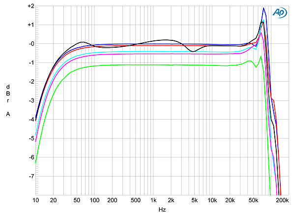
The EHF-100's output impedance from the single pair of Furutech binding posts per channel was low for a transformer-coupled tube design, at 0.49 ohm at 1kHz, rising to 0.6 ohm at 20Hz and dropping slightly to 0.4 ohm at 20kHz. As a result, the modification of the amplifier's frequency response by the usual Ohm's Law interaction between its source impedance and the modulus of impedance of our standard simulated loudspeaker (fig.1, gray trace) was a moderate ±0.25dB. The traces in this graph were taken with the volume control set to its maximum; commendably, there was no change in the measured response at lower settings of the control. Note also the excellent channel matching. There is a rolloff at low frequencies, reaching –1dB at 22Hz and –3dB at 12Hz. This is a deliberate design decision by Roger Gibboni, to "reduce transport low end rumble." More noticeable in this graph is the peaking between 70 and 80kHz. This is relatively mild, even into higher impedances, but it does result in a degree of overshoot and three cycles of ringing on the leading edge of a 10kHz squarewave (fig.2). The ringing was also evident in the leading edges of a 1kHz squarewave, which otherwise had an excellently square shape (fig.3).

Fig.1 Rogers EHF-100, frequency response at 2.83V into: simulated loudspeaker load (gray), 8 ohms (left channel blue, right red), 4 ohms (left cyan, right magenta), 2 ohms (green) (1dB/vertical div.).

Fig.2 Rogers EHF-100, small-signal 10kHz squarewave into 8 ohms.

Fig.3 Rogers EHF-100, small-signal 1kHz squarewave into 8 ohms.

Channel separation (not shown) was good, with any crosstalk in the midrange buried beneath the noise floor. The separation did decrease at higher frequencies, however, measuring 62dB, R–L, and 39dB, L–R. Of practical concern is a degree of inter-input crosstalk. With the second input selected but not connected to a source, feeding a 1kHz tone into the first input so that the output level would have been 1W into 8 ohms, resulted in an output level at –50dB ref. 1W. With a 20kHz tone at the same level, the inter-input crosstalk lay at –39dB. So if you have an FM tuner turned on and connected to one input while you listen to another input, a wispy-sounding ghost of the FM signal may be audible during quieter passages, depending on the tuner's source impedance. The solution will be to turn off other active sources, or to connect unused inputs to ground with shorting plugs.

The unweighted, wideband signal/noise ratio, ref. 1W into 8 ohms and taken with the input shorted and the volume control at its maximum—very much a worst-case situation—was different in the two channels, the right channel measuring a good 67.7dB but the left channel 57.75dB. Switching in an A-weighting filter improved these ratios to 83.0 and 79.2dB, respectively.

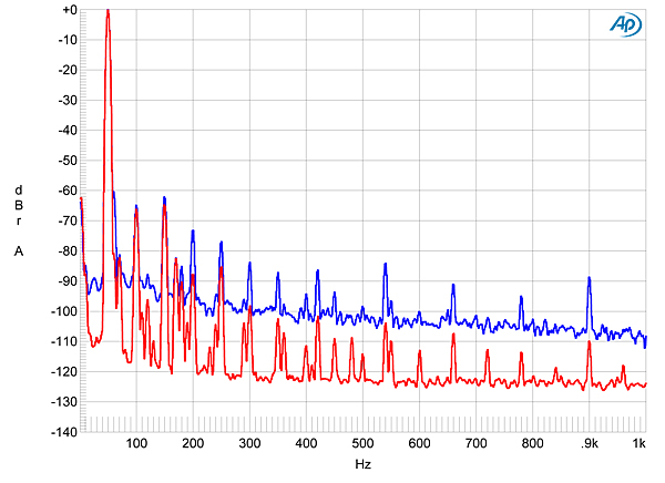
I experimented with the grounding between the amplifier and the Audio Precision test system, but couldn't get any improvement in the measured S/N ratio for the left channel. The noise level also didn't change when I swapped the output and small-signal tubes from one channel to the other. Fig.4, the spectrum of the EHF-100's low frequencies while it drove a 1kHz tone at 1W into 8 ohms, reveals that the primary difference between the channels is a higher level of 60Hz and its odd-order harmonics in the left channel (blue trace) than in the right (red). While some even-order harmonics of the AC frequency are present, stemming from internal grounding issues with a full-wave–rectified power supply, these lie at a relatively low level, though the lower sideband of the 1kHz at 880Hz (1000Hz–120Hz) can be seen at –83dB (0.007%). Odd-order AC-supply harmonics in an amplifier's noise floor generally arise from magnetic interference from the power transformer, but they also can be due to tube heater supplies, if these are fed 60Hz current. However, it is fair to note that AD didn't comment on any audible hum, though he did remark that there was "mechanical transformer noise."

Fig.4 Rogers EHF-100, spectrum of 1kHz sinewave, DC–1kHz, at 1W into 8 ohms (left channel blue, right red; linear frequency scale).

As well as differing in their noise levels, the two channels were slightly different when it came to linearity. I have therefore plotted how the EHF-100's THD+noise percentage varied with power level from the quieter, more linear right channel. Fig.5 shows the behavior into 8 ohms, fig.6 that into 4 ohms. fig.7 that inot 2 ohms. Both graphs indicate that the actual THD starts to emerge from the noise floor between 2 and 3W, with a gentle rise above that level suggesting a modest degree of loop negative feedback.

Fig.5 Rogers EHF-100, distortion (%) vs 1kHz continuous output power into 8 ohms (left channel blue).

Fig.6 Rogers EHF-100, distortion (%) vs 1kHz continuous output power into 4 ohms (left channel blue).

Fig.7 Rogers EHF-100, distortion (%) vs 1kHz continuous output power into 2 ohms (left channel blue).

Defining clipping as 1% THD+N, these graphs show that the EHF-100 clips at 35W into 8 ohms (15.4dBW) and 57W into 4 ohms (14.6dBW). Given that the amplifier clips at 36W into 2 ohms (9.5dBW), these figures suggest that the EHF-100's output transformer, as supplied for review, is optimized for a 4 ohm load. These powers are all lower than the specified 65W into 8 ohms (18.1dBW), though relaxing the definition of clipping to 3% THD+N allows the 4 ohm delivery to get close, at 60Wpc (14.8dBW). The measurements of the review sample supplied by Roger Gibboni indicate that it does meet its specified power of 65W, so I'm not sure why my measurements are different, though, at a fraction of a dB, the shortfall is relatively insignificant.

However, Gibboni's measurements do indicate that the left channel of this EHF-100 is both noisier and slightly less linear than the right. Fig.8 plots the THD+N percentage against frequency at a level—6.2V RMS, equivalent to 5W into 8 ohms, 10W into 4 ohms, and 20W into 2 ohms—where I could be sure that I was measuring distortion rather than noise. The left channel (blue, cyan, and gray traces) is significantly less linear than the right (red and magenta), perhaps due to aging and thus slightly mismatched KT88 output tubes. The THD+N figure rises in the bass due to the output transformer cores starting to saturate, but this is relatively mild in degree compared to typical tube amps, suggesting good transformer design. As expected, the THD+N rises as the load impedance drops, and also rises in the mid-treble and above, due to the circuit's decreasing gain-bandwidth product in this region.

Fig.8 Rogers EHF-100, THD+N (%) vs frequency at 6.2V into: 8 ohms (left channel blue, right red), 4 ohms (left cyan, right magenta), 2 ohms (left gray).

The lower trace in fig.9 shows the waveform of the THD+N residual, which is heavily second-harmonic in nature. Fortunately, the second harmonic is subjectively innocuous. The spectrum of the EHF-100's output while it drove a 50Hz tone at 10W into 8 ohms (fig.10) reveals both the higher noise floor and the higher level of the second harmonic in the left channel (–53 vs –68dB, blue trace), while the third harmonic is the highest in level in the right channel, at –64dB (0.06%). This level of third harmonic is due, as mentioned earlier, to the output transformer beginning to saturate.

Fig.9 Rogers EHF-100, 1kHz waveform at 9W into 4 ohms (top), 0.172% THD+N; distortion and noise waveform with fundamental notched out (bottom, not to scale).

Fig.10 Rogers EHF-100, spectrum of 50Hz sinewave, DC–1kHz, at 10W into 8 ohms (left channel blue, right red; linear frequency scale).

Although three of the four KT88 output tubes were numbered, there is no indication of what these numbers correspond to. I therefore experimented with swapping tubes around. Fig.11 shows the best result I obtained with the 50Hz tone, with now the levels of the second and third harmonics identical in the two channels. At higher frequencies, the second harmonic predominates in both channels (fig.11). Finally, despite the EHF-100's decreasing linearity at high frequencies, it did relatively well on the high-frequency intermodulation test (fig.12), all intermodulation products lying at or below –60dB (0.1%), though the power-supply spuriae in the left channel (blue trace) make their presence known.

Fig.11 Rogers EHF-100, spectrum of 50Hz sinewave, DC–1kHz, at 10W into 8 ohms after shuffling output tubes (left channel blue, right red; linear frequency scale).

Fig.12 Rogers EHF-100, HF intermodulation spectrum, DC–24kHz, 19+20kHz at 10W peak into 8 ohms (left channel blue, right red; linear frequency scale).

I was intrigued by the Rogers High Fidelity EHF-100; other than a home-brewed tube amplifier I constructed in the early 1980s, the only other amplifier I have encountered that used an EF86 pentode as the first stage was the classic Quad II monoblock. I had always wondered why the EF86 wasn't more popular with designers, as its combination of high voltage gain and low noise is unique; and while some have said that the tube is microphonic, it wasn't any more so than the ubiquitous 6DJ8/ECC88/6922, I found. Overall, the EHF-100 measures well for a classic design using a pair of KT88s as output tubes for each channel. However, the difference in noise floor between the two channels suggests that the circuit layout for the left channel could be further optimized.—John Atkinson

COMPANY INFO
Rogers High Fidelity
52 Kain Road
Warwick, NY 10990
(845) 987-7744
ARTICLE CONTENTS

COMMENTS
smittyman's picture

Probably is since no one else has commented.  But I have to raise a Spockian eyebrow at a giving a Very High Recommendation to a component whose volume control gets so hot it uncomfortable to touch after only an hour of use.  It shouldn't get that hot after any amount of use.  Surely that has to raise some doubt as to the basic usability of the thing; I mean we are talking about the volume control not a heat sink or the back cover.  This is a $6K amp - my $400 Fatman amp doesn't overheat like that.  Taking it a step further, doesn't it suggest a design flaw if heat is being dissipated through a user control?  If the volume control is that hot, how much heat is the rest of it giving off?
mrplankton2u's picture

Nope. You could get a quieter, higher powered, and arguably better sounding garden variety Onkyo amp for $400 - $500 - less than one tenth the cost of this turd. And in the extremely unlikely chance that your volume control got slightly warm to the touch after several hours of operation, your local Onkyo dealer would gladly exchange it for one that didn't have that problem. 

This amp, and the magazine that's "reviewing" it is a joke. Seriously, a $6,000 amp that has FM-like noise levels, no balanced inputs, and can barely deliver 60 watts without distorting heavily? 

And of course, Stereophile's resident advertising agents/manufacturer spokespersons chime in with the usual BS and blather:

"I was especially impressed by the EHF-100's overall musicality—a word I mean literally, not as a coded term for a particular sort of tonal balance: Not only did the EHF-100 sound good, it did a better-than-average job of playing music. Lines of notes had very good momentum and flow, suffering none of the temporal distortions of lesser gear (of any price)"... -Dudley


At least he didn't say "it had good pace and rhythm"...


"Overall, the EHF-100 measures well for a classic design using a pair of KT88s as output tubes for each channel." - Atkinson

Yeah, it's a horse drawn carriage and while it might not be a 2011 Mercedes V-12, it measures well for a horse drawn carriage. "Very highly recommended"...blah...blah...blah...

X