| Columns Retired Columns & Blogs |
May be JA1 could keep the JC1+ for a while (or, the Classe Delta monos), and review the new Magico A5 speakers :-) ........
I tested the Parasound Halo JC 1+ with my Audio Precision SYS2722 system (see the January 2008 "As We See It"). I preconditioned the amplifier by operating it at one-third the specified power into 8 ohms for an hour with the output-stage bias set to Normal. (With a class-AB output stage, one-third power results in the maximum dissipation in the output devices.) At the end of this time, the side-mounted heatsinks were hot, at 116.7°F (47.1°C). The top panel was a little cooler, at 98.9°F (36.7°C).
The Parasound's voltage gain into 8 ohms, set to Normal, measured 29.2dB from the balanced inputs, 29.4dB from the unbalanced inputs. Switching the gain to Low reduced both gains by 6.4dB. The amplifier preserved absolute polarity (ie, was noninverting) with both balanced and unbalanced input signals. Although slightly lower than specified, the balanced input impedance was still very high, at 92k ohms at 20Hz and 1kHz, dropping to 89k ohms at 20kHz. The unbalanced input impedance was 44k ohms at low and middle frequencies, 36k ohms at the top of the audioband.
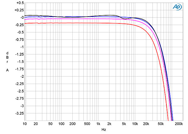
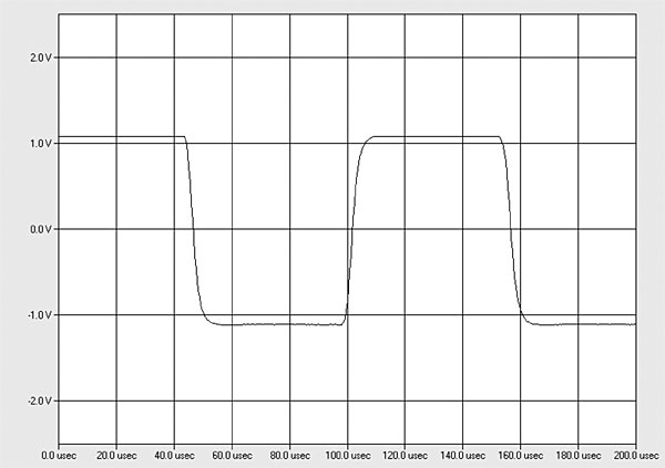
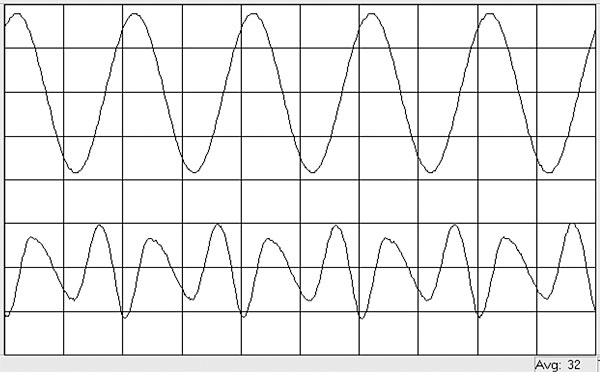
The Parasound's output impedance was a very low 0.067 ohm at 20Hz and 1kHz, increasing slightly to 0.085 ohm at 20kHz. (Though these impedances are higher than specified, they include the series impedance of 6' of spaced-pair loudspeaker cable, which I have estimated as 0.011 ohm.) The modulation of the amplifier's frequency response due to the Ohm's law interaction between this source impedance and the impedance of our standard simulated loudspeaker was negligible, at ±0.1dB (fig.1, gray trace). The response into an 8 ohm resistive load (fig.1, blue trace) was down by 3dB just below 100kHz and was flat to almost 20kHz, which correlates with the JC 1+'s superb reproduction of a 10kHz squarewave (fig.2). Commendably, there was no overshoot or ringing with the squarewave response.
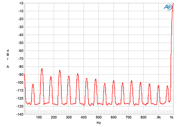
Measured with the unbalanced inputs shorted to ground and the bias set to Normal, the amplifier's unweighted, wideband signal/noise ratio was an excellent 75.8dB ref. 1W into 8 ohms, this ratio improving to 87.25dB when the measurement was A-weighted and to 114dB when referenced to the amplifier's specified clipping power. Low-level spuriae at the 60Hz power-supply frequency and its harmonics were present in the Parasound's noise floor (fig.3).
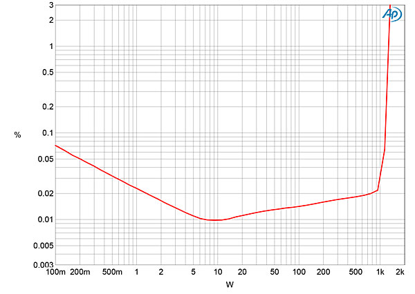
The JC 1+ is specified as being able to deliver 450W into 8 ohms (26.5dBW), 850W into 4 ohms (26.3dBW), and 1300W into 2 ohms (25.1dBW), all at 0.15% distortion. Using our definition of clipping, which is when the output's percentage of THD+noise reaches 1%, the Parasound exceeded its specified powers into 8 ohms, clipping with a 1kHz signal at 500W into 8 ohms (27dBW, fig.4). It didn't quite meet its specified power into lower impedances, clipping at 830W into 4 ohms (26.2dBW, fig.5) and at 1200W into 2 ohms (24.8dBW, fig.6). However, it is fair to note that I don't hold the AC wall voltage constant when I test an amplifier's clipping power. With the Halo JC 1+ idling, the wall voltage measured 121.8V. With the amplifier clipping into 4 ohms, the supply voltage had dropped to 119.4V, which explains the slight shortfall in maximum power.
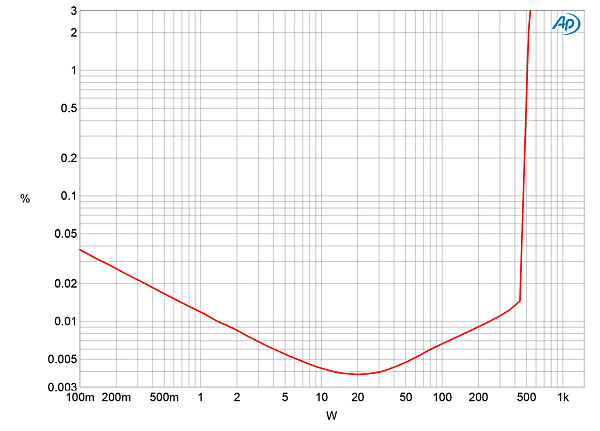
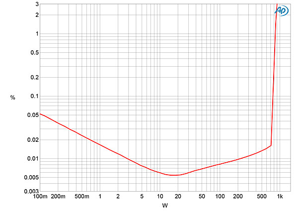
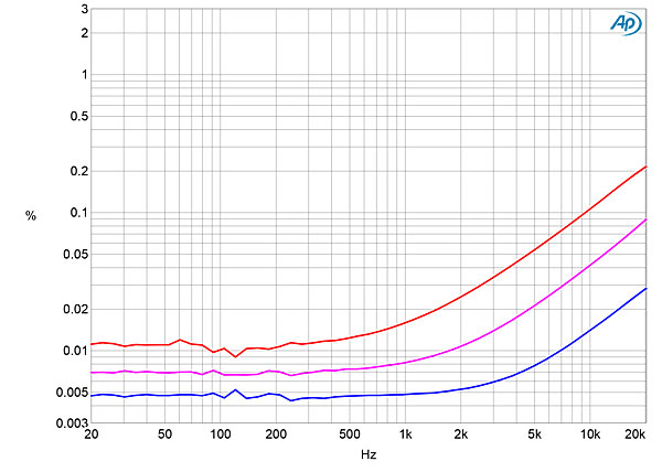
The shape of the traces in figs.4–6 suggested that, below a few tens of watts, the measured THD+N percentage was dominated by noise. I therefore examined how the percentage of THD+noise changed with frequency at 20V, which is equivalent to 50W into 8 ohms, 100W into 4 ohms, and 200W into 2 ohms. The THD+N was very low in the midrange into 8 ohms (fig.7, blue trace) but rose both into lower impedances (magenta and red traces) and at higher frequencies. Even so, other than at 200W into 2 ohms (red trace), the THD remained below 0.1% up to the 20kHz limit of this graph.
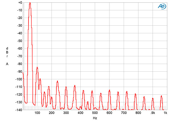
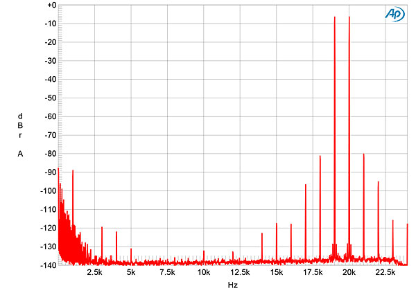
The JC 1+'s distortion was predominantly the subjectively innocuous second harmonic (fig.8), and higher harmonics are all very low in level (fig.9). The second harmonic lies at a low –86dB in this graph (0.005%) and didn't rise in level when I reduced the load impedance to 4 ohms. When the amplifier drove an equal mix of 19 and 20kHz tones at 100W into 4 ohms (fig.10), the second-order difference product at 1kHz lay at a very low –89dB (0.003%), though higher-order intermodulation products were slightly higher in level.
Like its predecessor, the Parasound JC 1+ offers a lot of low-noise, low-distortion power, and it is safe to say that its distortion signature will have no effect on the amplifier's sonic character.—John Atkinson
|
|
| ||||||||||

May be JA1 could keep the JC1+ for a while (or, the Classe Delta monos), and review the new Magico A5 speakers :-) ........
I (JA2) was scheduled to review the A5 for our August issue, but when California was shut down, my review pair had not yet been built, so the review was postponed indefinitely.
Jim Austin, Editor
Stereophile
Hopefully, they could be built during the 3rd quarter ........ Hopefully, you (JA2) could review and publish that review before the end of the year ....... My guess is, they are worth the wait :-) .........
I await them eagerly. Meanwhile, I'll have to make do with the M2s I have here at the moment. :-)
Jim Austin, Editor
Stereophile
You could compare them to M2s and also, the Revel Salon2s :-) .......
You (JA2) could do follow up review(s) of the JC1+ and/or the Classe Delta monos with M2s, while waiting for A5s :-) .........
If you (JA2) do a follow-up review of JC1+, may be you could also do a review of the Parasound top model, JC2 BP pre-amp ($4,500) :-) .......

If you (JA2) do a follow-up review of JC1+, may be you could also do a review of the Parasound top model, JC2 BP pre-amp ($4,500) :-)
Kal Rubinson reviewed the Halo JC2 BP in 2011. See www.stereophile.com/content/music-round-47-page-3.
John Atkinson
Technical Editor, Stereophile
Thanks ...... I missed that review ....... JA2 could still do a follow-up review of JC2 BP with JC1+ :-) ........
Thanks for a great review, John - I thoroughly enjoyed reading your write up. I have had a few Parasound products over the years and currently own a P6 paired with a JC 5 power amp. The latter is the
best power amp I have ever owned and paired with a pair of Monitor Audio Gold 300s, the sound is sublime! I wonder how different a pair of JC 1+ would sound in my current system; anyway, Well done, Mr. Curl is all I want to say as well for delivering the JC 5 - simply a most fantastic amplifier. Someday maybe I will own pair of the the JC1 + :) ..
I must also say, that the Gentlemen I have had the pleasure to interact with at Parasound, mostly for
product knowledge and to leverage their general audio experience, are simply wonderful.
... comparison with the JC 1+ a ~17-year-old unit?
If so, was any effort made to determine (as by measurement) whether or not its performance had deteriorated with time?
It's not inconceivable that a nearly 20-year-old amplifier might need to have certain parts (such as electrolytic capacitors) replaced.
It's also disconcerting to find out that Mr. Curl/Parasound decided to incorporate obsolete devices into a new/updated product offering. None of the companies I've worked for would tolerate such a situation. Obsolete parts are only to be inventoried for use as service spares, not for current production units.

in what engineering realm does "no-longer-manufactured" mean "obsolete" ???
Why do you think so many great/legendary amp designer's stockpile these JFETs (and other extra-ordinary parts)?
https://www.stereophile.com/content/gramophone-dreams-26-nelson-pass-harmonic-distortion
hr
Ortofan's 'weaponized adjectives' are mild compared to some others, on Stereophile website :-) .......
... really HR? That characterization seems a tad extreme.
"No-longer-manufactured" means "obsolete" in every engineering "realm" I've been associated with for the past 40 years.
Just one example of the usage of that term:
https://www.analog.com/cpsearch/crossreferencesearch.aspx
Would you find the phrases "not for new design" or "end of life" less offensive?
Why do "so many great/legendary amp designer's stockpile these JFETs (and other extra-ordinary parts)?"
Likely because they would rather not go to the expense and effort required to find suitable replacement devices, redesign circuits and circuit boards as necessary, possibly reprogram the assembly equipment if automated assembly is used, update the documentation, get the products re-certified by regulatory agencies, and so on. Maybe the companies for which these "great/legendary amp designers" work don't have a sustaining engineering department whose function includes the redesign of existing products when certain components become "obsolete". For a relatively low volume application, making a "lifetime buy" of "obsolete" devices may be the more economical and expeditious route. However, that's never been considered an acceptable practice for any of electronic products with which I've ever been involved.
JA1's review of Classe Delta monos is coming soon in Stereophile ....... May be JA1 describes how the new, more modern Classe, class-A amps are designed ...... and, how the Classe monos compare with JC1+, in sound quality :-) .......
Some people take the 'don't mess with success' approach :-) .......
Why do "so many great/legendary amp designer's stockpile these JFETs (and other extra-ordinary parts)?" Likely because they would rather not go to the expense and effort required to find suitable replacement devices...
When I discussed the subject with the late Charley Hansen some years ago, the problem is that there weren't any replacement parts. Apparently the semiconductor fabs no longer manufacture high-performance but low-profit, complementary, small-signal J-FETS that get anywhere close to the performance of those used by Parasound, Ayre, and others. Charley therefore spent a very large sum buying up as much as he could afford of the world's supplies of these devices.
John Atkinson
Technical Editor, Stereophile
... totally stymied if a favorite component becomes "unobtanium"? If they are, indeed, truly "great/legendary", shouldn't it be well within their capability to develop an alternate design that uses more readily available devices?
ROHM once made fabulous bipolar transistors, with exceptionally low base spreading resistance, that were ideal for a moving-coil cartridge phono preamp. In the days of CRT-type HDTV sets, Sanyo and Panasonic produced high-voltage transistors, with very low collector output capacitance, that were well suited for use in the driver stage of an audio power amp. Those specific parts are all gone and they're not coming back. Linear Systems presently makes some low-noise JFETs and Sanken makes some transistors for audio driver applications. Neither are necessarily drop-in replacements for "obsolete" devices, so some redesign effort could well be required to convert to their use. Marantz's Ken Ishiwata used to comment on the matter of staying on top of device obsolescence and identifying acceptable replacements, while performing redesigns, as needed.
I've seen more than one case where the last-time-buy didn't last a lifetime. Those involved took the easy (or lazy) way out and hoped that they would no longer be working at the same company - either because they had changed employers, retired or died - by the time that the "lifetime" supply was exhausted.
Again, it's disappointing to see that a decision was made to incorporate obsolete devices into a newly updated product offering - especially one that seems to be on a decades long life cycle. It's curious to note that some tube amp consumers, by comparison, seem to have no qualms about the use of new-old-stock/out-of-production parts. Maybe that trend is spreading into the solid-state "realm"?
Two comments:
1. There are precious few companies making JFETs these days. The market just isn't there. This is especially true for P-channel devices, which are harder to make with low noise properties. Most of the JFETs available now are based on decades old processes that have been kept alive for some high priority customers. That doesn't include the audiophile product business.
Linear Systems has really done yeoman's work in providing JFETs for specialized industries. At least in the JFET world relevant to this discussion, much of their activity has been to clone the Toshiba designs. It's hard, again especially for P-channel devices. Toshiba had the process knocked, and produced them by the freight car load. There was that much demand and the prices were quite literally pennies per transistor. Linear Systems doesn't have that available market, so the prices are inevitably going to be much higher, both due to basic economics and the yield challenges. (You make a zillion devices and you learn the subtleties of the recipe.)
The trend now is for entire systems to be built into a single chip. That's where the money is. If a company gets a design win for a single cell phone audio system, that's bigger for that semiconductor company than if they got every sale of every semiconductor for the entire specialty audio market. By a large factor.
Something to consider...
2. Along the same lines, consider the age demographic of the guys (it's almost exclusively men) who are doing analog design for audio. It pretty much parallels the age demographic of the people who buy the finished product. What will happen when they decide to retire?
When I was in college, at your basic nerd school, it seemed like every EE major wanted to go into the audio business. Of the entire student body when I was there, as far as I know a total of three did go into the audio business. They all were management engineering majors, and the three focused on the business subjects that were part of that curriculum.
With the consolidation of system functions onto a single chip, that means that far fewer analog design guys are needed. That's been the trend for a while. The semiconductor providers also do much of the design work so that their customers don't need many analog design guys, not only for audio but for any analog application. That's probably a good thing, in a way, since the young people studying electrical engineering mostly aren't all that interested in analog or RF design. It's the circle of supply and demand.
Something else to consider...
Five to ten years from now, all audio amplifiers are gonna be class-D ...... Five to ten years from now, people will be listening to wireless speakers with built-in class-D amps, in addition to various Bluetooth devices :-) .........

Thanks CG, nice points
Dunno!
If you're paranoid enough, you could make the same arguments about bipolar output devices suitable for audio use, too. And a bunch of the other parts. Maybe that's not paranoia - just being realistic. I bet the tube guys had similar thoughts back in the boom days of tube based amplifiers.
In any case, if there's nobody interested in designing new gear, it won't matter, will it?
... is that many (small-signal, and even medium power) devices, that were once available in leaded/through-hole packages, may now only be produced in surface-mount packages. Aside from the need to create new circuit board layouts and have SMT/SMD assembly capability, certain audio companies would have us believe that leaded/through-hole parts are "good" and that surface-mount parts are "bad".
If those companies have no choice other than to switch to using at least some surface-mount parts, then they would need to retract their previous assertions about the alleged inferiority of surface-mount technology.
I'm not sure that is accurate.
Many audio companies have already switched to surface mount semiconductors where the package is available.
The problem has to do with some of the passive components. There just isn't the ready availability of film caps in the varieties found with through hole components. Some will likely never be available in surface mount packages due to not only the size, but also the thermal constraints during surface mount soldering. Also, there is far less of a selection of low noise, low distortion resistors in surface mount packages. (Bruce Hofer, who certainly can be considered an expert on the topic, has written about this.) That inferiority is not "alleged"..
So, companies are then left with the choice of sonic compromise or to use mixed manufacturing technologies. Combining both surface mount and through hole components on the same printed circuit board assemblies can certainly be done, but it costs more. I'm sure audio companies would like to save money where they can, IF it gave them the same or better results.
... quite adequate, unless you want to specify a particular boutique brand of capacitor in order to help validate your creation or lend it a certain cachet in the marketplace.
Likewise, for resistors, unless perhaps you're in the business of building test equipment. Funny how the tube amp makers all seemed to manage when resistors were mostly of the carbon composition type.
Well...
You are certainly entitled to your opinion on this. I disagree. Try finding polystyrene caps in surface mount. Not so easy. These types of caps have been measured to provide lower distortion in many circuit locations.
In general, I've noticed from you a certain hostility toward everybody in what I'll call the high performance audio business. This is shown in almost all of your posts. Again, you are completely entitled to your own thoughts on the business and the people who work in it.
This is not a good discussion. I hope you don't take offense when I decline to respond further.
... to the function of your design, or might PPS type capacitors - available in SMT for from WIMA and Panasonic, to name two - be satisfactory?
Over 30 years ago, Hafler introduced the XL-280 power amplifier and claimed that it had the lowest residual according to a bypass test. To my knowledge, no one has ever stepped up to challenge that claim. The XL-280 accomplished that feat without resorting to the use of any exotic components. If an output capability of about 160W@8Ω/225W@4Ω was insufficient, there was the more powerful XL-600. An XL-600 would clip at about 370W, 680W and 900W into 8Ω, 4Ω and 2Ω, respectively. The XL-600 sold for $1,200 - or about $2,800 as adjusted for inflation today.
Similarly, QUAD has been producing its "straight wire with gain" amps for decades with out using exotic parts, either.
Essentially, do you want your amplifier to exhibit a certain subjective sound quality, or do you want it to be as neutral and self-effacing as possible? If you want a neutral amp, then it's been demonstrated that the use of exotic types of components is not a requirement to achieve that goal.
Probably, the Benchmark AHB2 is similar in concept, as those Hafler amplifiers :-) ..........
The new Hafler company still makes power amps ........ See, their website for details :-) .........
Ortofan, Rotel says, in their Michi amps they use 'patented slit foil, low ESR capacitors' ........ Do you know anything about them? :-) .......
... slit-foil type electrolytic capacitors for quite some time.
You can read about the technology here:
http://www.dnm.co.uk/capacitors.html
The slit-foil caps were originally sourced from BHC, which was acquired by Vishay/Kemet. Kemet still offers some parts of that type:
https://content.kemet.com/datasheets/KEM_A4029_ALC10S.pdf
https://sh.kemet.com/Lists/ProductCatalog/Attachments/632/KEM_A4030_ALN20S.pdf
According to the DNM site, the slit-foil caps may also be available from Taiwanese company Supertech:
http://www.supertech-elec.com.tw/electronic/ECAPS/Audio-2T.htm
http://www.supertech-elec.com.tw/electronic/ECAPS/Audio-4TTN.htm
That total capacitance figure of 22,400 on page 1 sure seems low. Are you sure it’s not 224,000?

I owned a pair from about 2006 to 2019 and used them with two different highly regarded speaker systems. No other amp delivered as much musical enjoyment as the JC1s with either speaker. I utilized the low bias setting for background music and hi bias for active listening. Heat was never an issue.
The only reason I no longer own them is because they have far more power than now needed, plus at my age they were becoming a little heavy whenever I needed to move them. I can only imagine the new model must be exceptional.
Thanks John, great review. Any thoughts about how the SQ compares to your Pass Labs XA60.8 amps?
Any thoughts about how the SQ compares to your Pass Labs XA60.8 amps?
JA1 doesn't have the XA60.8s. JA2 does.
Jim Austin, Editor
Stereophile
Which begs the question, 'any thoughts about how the SQ compares to your Pass labs XA60.8 amps' JA2? :-) ..........
Regrettably, I haven't had the opportunity to hear the JC 1+. Hopefully I will at some point in the reasonably near future.
Jim Austin, Editor
Stereophile
at the same price but much lower weight
Bridged AHB2s cost less than Pass XA60.8 or JC1+ :-) ........
Comparison between bridged AHB2s and JC5 would be interesting :-) .......

Probably better than any other $17k amp/s around.
Cheers George
Not if Class-D and the environment has anything to do with it.
Maybe the Technics SE-R1 had a shot?
(Bit like exotic V8 V10 V12 muscle cars) I'm now driving a 2lt twin turbo buzz box, JUST NOT THE SAME!!!
Cheers George
You can still buy a V8 Mustang, Camaro and Corvette :-) .........
In Australia that'll cost you a kidney a lung and left testicle. $$$$$$$$$$.
Cheers George
So, in Australia, if some one wants to buy an Aston Martin Vanquish or Lamborghini Aventador with V12 engines, that would cost them both kidneys, both lungs and both testicles :-) .......
And if you want the Veneno Roadster, your body and soul is the price.
https://cdn.motor1.com/images/mgl/A80qL/s1/2014-lamborghini-veneno-roads...
Poison ......
Venenosaurus :-) .......
Armando the racing pigeon sold for $1.4 million in 2019 :-) ..........
Nothing a BB gun wouldn't take care of.
All box speakers with dynamic drivers in them have distortion levels at least ten times that of any power amp. Therefore it is impossible to hear amplifier distortion thru this type of speaker. The amp's distortion is completely masked by the much greater speaker distortion. This is why discussions about the "sound quality" of amps are absurd. What these reviewers are actually hearing are the speakers, not the amp.


| Loudspeakers Amplification Digital Sources | Analog Sources Accessories Featured | Music Columns Retired Columns | Show Reports | Features Latest News Community | Resources Subscriptions |
 © 2024 Stereophile


