| Columns Retired Columns & Blogs |
Marillyn Crispell CD is a nice addition to a jazz collection. Too bad I will never hear it on the Nagra Jazz. A nice looking amp; it's from Switzerland!!
I measured the Nagra Jazz preamplifier with Stereophile's loan sample of the top-of-the-line Audio Precision SYS2722 system (see www.ap.com and the January 2008 "As We See It"). The review sample had only unbalanced inputs but was fitted with the optional balanced output transformers. I therefore performed a complete suite of measurements from both the unbalanced and balanced outputs, though in the following text I have concentrated on the balanced outputs, as that is how Bob Reina used the Jazz for his auditioning.
The voltage gain at 1kHz was 11.65dB from both sets of outputs with the front-panel switch set to +12dB, and –0.25dB with the switch set to 0dB. A reading of "0dB" on the Jazz's front-panel modulometer corresponded to 1V output into 100k ohms. Both outputs preserved absolute polarity (ie, were non-inverting), the XLR jacks being wired with pin 2 hot. The input impedance was lower than specified but was still usefully high at 51k ohms at low and middle frequencies, dropping slightly but inconsequentially to 39k ohms at 20kHz. The unbalanced output impedance was 116 ohms at 20 and 1kHz, rising slightly to 251 ohms at 20Hz. The balanced output impedance was 295 ohms at 20Hz, dropping to 158 ohms at 1kHz and rising again to 186 ohms at 20kHz. All of these impedances are usefully low in absolute terms, though are a little higher than specified.
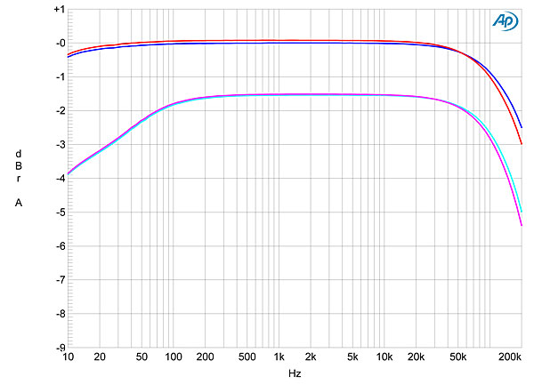
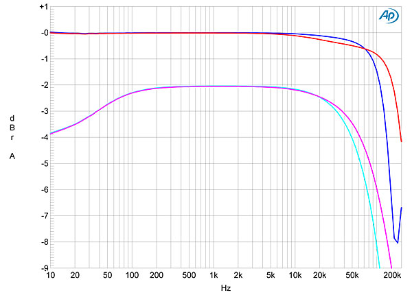
Fig.1 shows the Jazz's frequency response at 1V with the volume control set to its maximum and the balance control centered, measured at the unbalanced output into 100k ohms (blue and red traces) and into 600 ohms (cyan, magenta). The bandwidth is very wide into both loads, with the output down by 3dB at 200kHz, and the channels are very closely matched. The low frequencies start to roll off a little into 600 ohms, but so extreme a load is unlikely to be encountered in practical use. Fig.2 shows the response under than same conditions measured from the balanced outputs. It's still flat in the audioband, but rolls off earlier into the low impedance, reaching –3dB at 60kHz (left channel, cyan trace) and 85kHz (right channel, magenta trace). The high-frequency rolloff is also different between channels into the high impedance, with a major difference visible above 100kHz, though of course this will have no audible consequences. Commendably, the close matching between the channels was maintained at lower settings of the volume control, a tribute to the quality of the ALPS potentiometer used. The audioband frequency response was identical for the 0dB and +12dB gain settings.
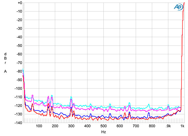
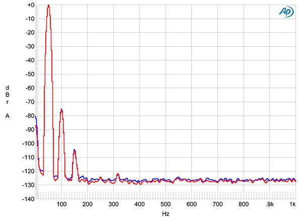
Channel separation was good rather than great, at >80dB in both directions below 1kHz but about 50dB at the top of the audioband (not shown). I measure signal/noise ratios (SNRs) with the input shorted but with the volume control set to its maximum, which is very much the worst-case situation. The wideband, unweighted SNR, ref. 1V output, depended on the gain setting. With the gain set to 0dB, the ratio was 70.2dB (average of two channels), while switching the gain to +12dB decreased the SNR by the same 12dB. Restricting the measurement bandwidth to the audioband increased the ratios to 103 and 90dB, respectively, which is excellent, while switching into circuit an A-weighting filter increased the measured ratios by 3dB. This is a very quiet preamp with power-supply spuriae all at or below –110dB, even at the +12dB gain setting (fig.3).
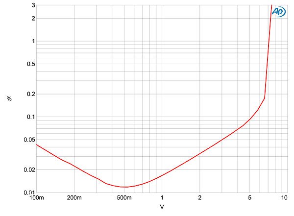
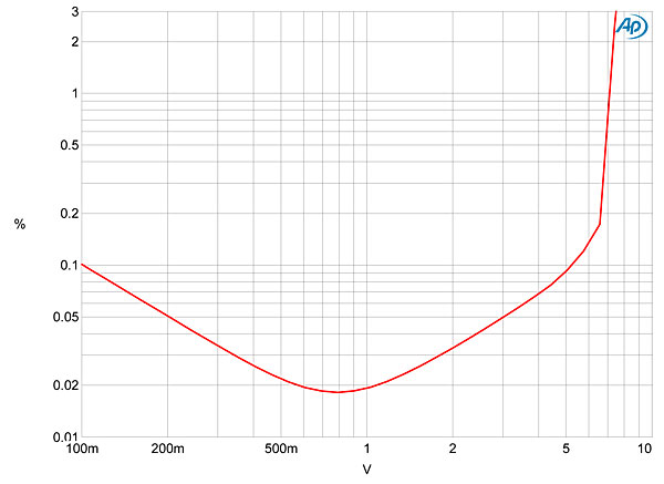
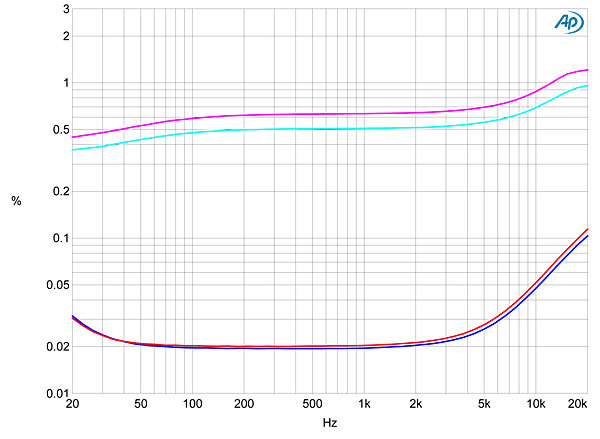
Figs. 4 and 5 show how the THD+noise percentage in the Nagra's output changes with output voltage from, respectively, the unbalanced and balanced outputs. The THD+N reading was dominated by noise below 500–600mV and remains very low at all levels the Jazz will be asked to deliver in normal use. The gain was set to 0dB for these measurements; switching to +12dB preserved the shape of the curves but increased the THD+N percentage below clipping (not shown). At 1V into 100k ohms from the balanced outputs, the Jazz offered very low distortion (fig.6, blue and red traces), though with a rise in the top two octaves. The preamplifier was clearly unhappy into 600 ohms (cyan and magenta traces); loads this low are to be avoided.
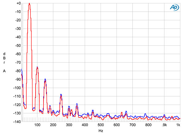
The distortion from the balanced output at 0dB gain was predominantly second harmonic (fig.7), though the third and fifth harmonics can respectively be seen at –90dB (0.003%) and –110dB (0.0003%). With the unbalanced output (fig.8), the second harmonic remained at –76dB (0.015%), but the third harmonic dropped to –114dB (0.0002%), and all higher-order harmonics disappeared. Switching to +12dB gain increased the levels of all harmonics by the same 12dB (not shown).
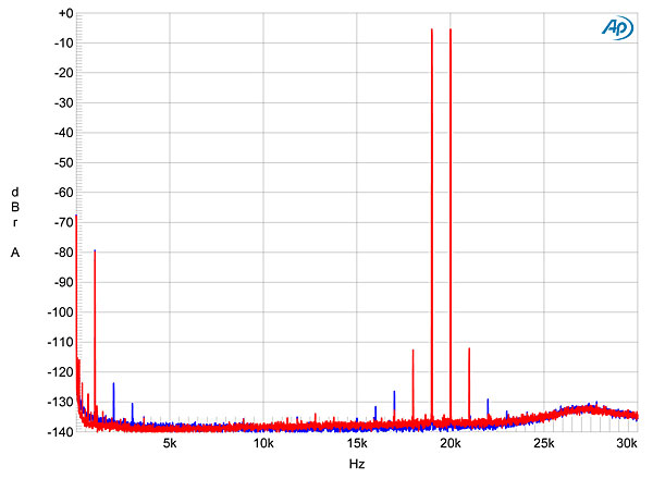
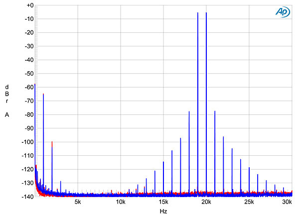
The unbalanced output offered a very low level of intermodulation distortion, with the difference product resulting from an equal mix of 19 and 20kHz tones lying at –80dB (0.01%), and the higher-order products all much lower in level (fig.9). The balanced outputs (fig.10) clearly showed that the output transformer's reduced linearity was beginning to affect the measured result, but not to the extent that there would be any subjective consequences.
The Jazz's excellent measured performance revealed it be as well engineered as I have come to expect from Nagra. And as a fan of the Swiss company's earlier PL-L preamplifier, which I reviewed in June 2008, I'm happy to see the input and output jacks moved from the side panels to the rear!—John Atkinson
|
| ||||||||||

Marillyn Crispell CD is a nice addition to a jazz collection. Too bad I will never hear it on the Nagra Jazz. A nice looking amp; it's from Switzerland!!

Hello;
Looks like a very nice component. Nagra gear always makes my heart pump. Great sounding too, going by the review.
I am confused. The review indicates that the input is differential, but later goes on to say that an optional transformer is required for differential. If the amplifier is configured to do balanced (differential), why do we need a transformer to utilze this?
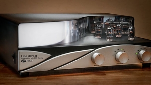
"If I had wandered inside, I would have discovered a 12AX7 dual-triode tube, one per channel configured in differential topology..."
"The Jazz's suite of inputs consists of one pair balanced (if the optional input transformers are fitted, otherwise this input is single-ended)..."
Any explanation?
Thanks
Vince


| Loudspeakers Amplification Digital Sources | Analog Sources Accessories Featured | Music Columns Retired Columns | Show Reports | Features Latest News Community | Resources Subscriptions |
 © 2024 Stereophile