| Columns Retired Columns & Blogs |
Monitor Audio Studio 2 loudspeaker Measurements
Sidebar 2: Measurements
Although the Studio 2's sensitivity is nowhere near the specified 89dB/W/m—I estimated it at 84.5dB/W/m, B-weighted—it's still quite high for such a small loudspeaker. Coupled with a highish impedance magnitude, which only drops below 6 ohms in the lower midrange (fig.1), the Studio 2 will give the partnering amplifier an easy time. The low-frequency trough in the traces in fig.1 reveals that the port is tuned to 65Hz. A slight wrinkle in the magnitude trace at 320Hz is probably due to a cabinet resonance.
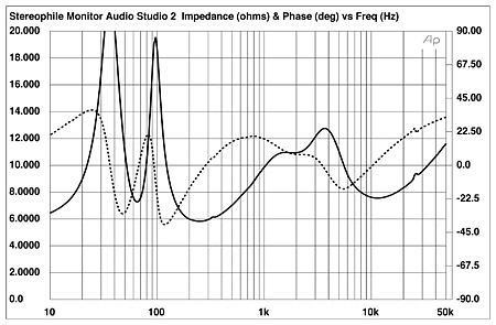
Fig.1 Monitor Audio Studio 2, electrical impedance (solid) and phase (dashed) (2 ohms/vertical div.).
Though the crossover filters are specified as first-order, 6dB/octave, low-pass on the woofer and second-order, 12dB/octave, high-pass for the tweeter, it actually looks more complex than that, with a total of three coils, four capacitors, and two resistors mounted behind the terminal panel. Tracing out the circuits revealed the tweeter filter to be indeed second-order, with a series 3.3 ohm resistor to lower its sensitivity to match that of the woofer. The woofer filter, however, appears to have started life as fourth-order, but is quite asymmetrical in that the first series inductor is a high-value, ferrite-cored type, the second smaller in value and air-cored. The first series capacitor is a high-value, non-polarized electrolytic and the second a low-value plastic-film type. In addition, the second coil is shunted with another plastic-film capacitor.
The resulting electrical responses, measured at the drive-unit terminals, are shown in fig.2. The tweeter drive features a rather over-damped second-order slope. The woofer drive signal is slightly sloped-down between 80Hz and 2kHz, presumably to compensate for the drive-unit's rising on-axis response. An initially gentle rolloff at crossover is followed by a sharp notch at 7.5kHz, which I assume is intended to kill a woofer cone-breakup mode at that frequency.
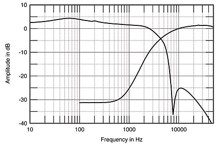
Fig.2 Monitor Audio Studio 2, crossover electrical drive signals (5dB/vertical div.).
Turning to the individual responses of the drive-units and port, fig.3 reveals that the latter's bandpass is centered on 70Hz, suggesting moderate bass extension—this is a small loudspeaker—with the port taking the primary responsibility for bass output below 100Hz. Higher in frequency, the woofer still features a small rise at the top of its passband, before rolling off steeply. There appear to be no significant cone-breakup resonances apparent in its output just above crossover, but note that there's a spike apparent at the 7.5kHz notch-filter frequency, this knocked down to lie 20dB below the nominal reference level. The larger-diameter metal-cone woofers in earlier Monitor Audio designs did feature a mode in the 5–6kHz region—see my review of the Studio 6 a year ago (Vol.17 No.2, February 1994, pp.98–106), for example—which emphasized sibilants and made the speaker rather fussy with recordings that were themselves treble-heavy. As WP noted, the Studio 2 sounds free from such problems.
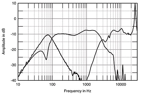
Fig.3 Monitor Audio Studio 2, acoustic crossover on optimal axis at 50" corrected for microphone response, with nearfield woofer and port responses plotted below 300Hz and 600Hz, respectively.
The tweeter comes in relatively slowly, and though it's rather unflat in response, the Studio 2's tweeter measures very similar to the other Monitor Audio designs in which it is used. (Again, see my Studio 6 review last February).
Even before I read the text of Wes's review, it was obvious that the traditional tweeter axis was not the listening axis, the Studio 2 sounding thin and sucked out. Initially, I suspected a drive-unit phasing problem, but as both samples sounded and measured identically, experimentation with the measurement axis was called for. Surprisingly, the flattest measured response (fig.4) was obtained below the bottom of the woofer, fully 15° away from the tweeter axis. These little speakers must be used on very tall stands, or even (horror!) on bookshelves, which makes it hard for me to believe that they will be given their best shot in a dealer's soundroom. Keep this in mind if you audition them in unfamiliar surroundings.
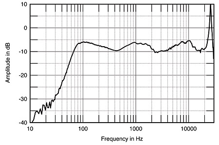
Fig.4 Monitor Audio Studio 2, anechoic response on optimal axis at 50" averaged across 30° horizontal window and corrected for microphone response, with complex sum of nearfield woofer and port responses below 300Hz.
The reason for the main response lobe to be tilted down in this fashion is that the tweeter is wired in the opposite acoustic polarity to the woofer. Flipping the phase of the tweeter moves the flattest response from an axis well below the loudspeaker to being on the tweeter axis. This can be seen in fig.5, where are shown the responses on the tweeter axis with the drive-units in and out of phase. As wired at the factory, the speaker features almost complete cancellation in the crossover region on this axis (lower trace). With the woofer polarity flipped (upper trace), the speaker can now be used on shorter stands without compromising its sound quality.
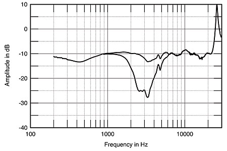
Fig.5 Monitor Audio Studio 2, anechoic response on tweeter axis at 50" with woofer acoustically in-phase (top) and out-of-phase (bottom) with tweeter, corrected for microphone response.
The actual response on the optimal axis is triple-humped, there being slight lacks of energy in the lower midrange and mid-treble. To the left of fig.4 is shown the complex sum—amplitude and phase—of the port and woofer outputs, weighted in the ratio of their diameters. The response extends to 60Hz, –6dB, which is actually pretty good bass extension for such a tiny speaker.
The Studio 2's change in response with vertical axis is examined in detail in fig.6, which just shows the changes in measured response as the listener moves above or below the optimal axis. As shown here more clearly, the speaker is only really evenly balanced below or well above the tweeter axis. Here, at last, is a speaker that will sound neutrally balanced for standing listeners!
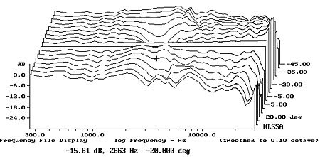
Fig.6 Monitor Audio Studio 2, vertical response family at 50", normalized to response on optimal axis, from back to front: differences in response 60°–5° above optimal axis; reference response; differences in response 5°–30° below optimal axis.
Horizontally, fig.7 reveals that fig.4's on-axis valley in the mid-treble fills in to the speaker's sides. Other than in the mid-treble, the Studio 2's overall response doesn't change much until the listener is more than 20° off-axis, even in the high treble. As always with small-baffled speakers, you get excellent horizontal dispersion.
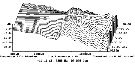
Fig.7 Monitor Audio Studio 2, horizontal response family at 50", normalized to response on optimal axis, from back to front: differences in response 90°–5° off-axis; reference response; differences in response 5°–90° off-axis.
In the time domain, the Studio 2's impulse response (not shown) is dominated by the ultrasonic ringing of the tweeter's metal dome. This, of course, should not be audible. The associated step response (fig.8), as indicated earlier, reveals that the tweeter and woofer are connected with opposite acoustic polarities. Flipping the woofer connection to give the flatter tweeter-axis response shown in fig.5 results in the step response shown in fig.9. Both drive-units have positive polarity, but the tweeter leads the woofer in time.
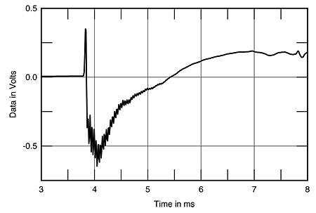
Fig.8 Monitor Audio Studio 2, step response on tweeter axis at 50" (5ms time window, 30kHz bandwidth).
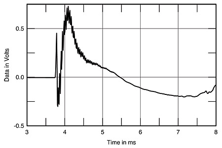
Fig.9 Monitor Audio Studio 2, step response on tweeter axis at 50" with inverted woofer polarity (5ms time window, 30kHz bandwidth).
The cumulative spectral-decay, or waterfall, plot (fig.10) is very clean, the speaker's balance remaining unchanged as the impulse quickly decays. The exceptions are the large resonance at 26kHz (the tweeter's ultrasonic "oil-can" mode), and a residual resonant mode at the 4.4kHz cursor position. Though this may be due to the woofer cone, it's well down in level and should have no audible effects.
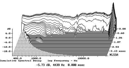
Fig.10 Monitor Audio Studio 2, cumulative spectral-decay plot at 45" (0.15ms risetime).
Finally, the impedance plot suggested the presence of a cabinet resonance between 300Hz and 400Hz. Using a simple plastic-film accelerometer to feed the MLSSA system's analysis input resulted in the waterfall plot shown in fig.11. This confirms the presence of a resonance at this approximate frequency, but, as expected from the Studio 2's small, rigid cabinet construction, it is well down in level and should not have any effect on sound quality.—John Atkinson
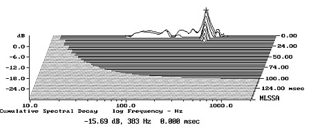
Fig.11 Monitor Audio Studio 2, cumulative spectral-decay plot of accelerometer output fastened to center of enclosure back panel. (MLS driving voltage to speaker, 7.55V; measurement bandwidth, 2kHz.)
- Log in or register to post comments
