| Columns Retired Columns & Blogs |
Mirage M-7si loudspeaker Measurements
Sidebar 2: Measurements
JA measured the Mirage M-7si with the DRA Labs MLSSA system and a calibrated DPS microphone; he provided me with the results following my listening tests.
As expected from the auditioning, the Mirage's sensitivity was estimated at a low 82.5dB/W/m (B-weighted). Its impedance is shown in fig.1. With a minimum impedance of 4.8 ohms at 130Hz, it should be a relatively easy load for any competent amplifier to drive. With its low sensitivity, however, you should take the manufacturer's minimum recommended power (50W) very seriously. And to really get the most from these loudspeakers, I would not recommend an amplifier of less than 100Wpc.
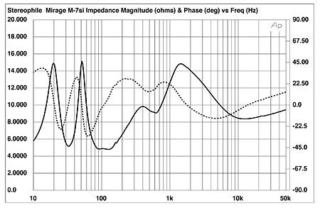
Fig.1 Mirage M-7si, electrical impedance (solid) and phase (dashed) (2 ohms/vertical div.).
The tuning of the M-7si's ports can be seen at a low 33Hz. A small wrinkle in the impedance-magnitude plot at about 175Hz may indicate a port or cabinet resonance. It falls in the middle of the Mirage's elevated warmth region, and I didn't find it audible.
To judge by the schematic published in the Italian magazine AUDIO Review, the Mirage's crossover is pretty complex for a two-way design. While the tweeter's high-pass filter is basically a third-order design, with a series resistor to reduce the tweeter sensitivity, the woofer's low-pass filter features two pairs of parallelled inductors and capacitors. As can be seen in fig.2, which shows the SPICE-modeled filter responses (assuming the drive-units to be 8 ohm resistors), this results in a drive signal with two broad notches rather than a simple low-pass function. Also shown in fig.2 is the filtered signal to the rear drive-unit. This features a first-order, 6dB/octave slope and appears to extend lower in frequency than the specified 480Hz; in fact, the –6dB point is two octaves lower at 100Hz. Note also that the rear-driver output is padded down by 10dB.
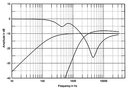
Fig.2 Mirage M-7si, crossover electrical drive signals (5dB/vertical div.).
Fig.3 shows the FFT responses of (from left to right) the combined sum of nearfield responses of both ports, the nearfield response of the woofer (below 300Hz), the anechoic response of the woofer measured at 52", and the 52" anechoic response of the tweeter. The ports' output is well below that of the woofer's in level, indicating a possible QB3 alignment. The woofer's motion is at a minimum at 33Hz—the same frequency to which the ports are tuned. The rise in the woofer's response between about 45Hz and 300Hz is real, but perhaps a bit less extreme than it appears here due to the levels at which the nearfield and anechoic responses were spliced. The notch in both port and woofer responses just under 175Hz coincides with the glitch in the impedance plot, and may relate to it. There's also a port mode present at about 600Hz.
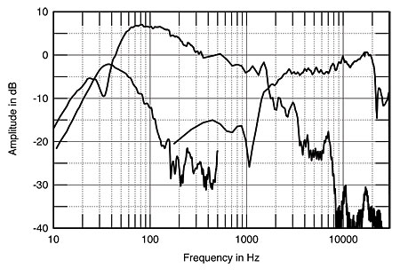
Fig.3 Mirage M-7si, acoustic crossover on tweeter axis at 52" corrected for microphone response, with nearfield woofer and port responses plotted below 300Hz and 600Hz, respectively.
The crossover frequency appears from fig.3 to be at about 1.8kHz—slightly lower than the specified 2kHz. There are also some rather ugly-looking breakup modes in the woofer's rolloff, or stop-band, response. However, except for the peak at 1.5kHz, these are progressively further down in level as their frequency increases.
Fig.4 shows the overall response of the M-7si—the complex sum of the nearfield woofer and port responses below 300Hz combined with the quasi-anechoic response at 52" averaged across a 30° window. Also shown (in the lower curve) is the response of the rear-facing MSE driver. The 6dB-down point of the overall response is at 33Hz. With typical room-gain, response to 30Hz can be expected. My listening guesstimate of response to well below 40Hz was conservative! The "generous" mid- and upper-bass response is clearly visible here, and indicates, as I noted in the review, that rooms having a tendency to emphasize this region themselves (unfortunately not all that uncommon) may be a problem for the M-7si.
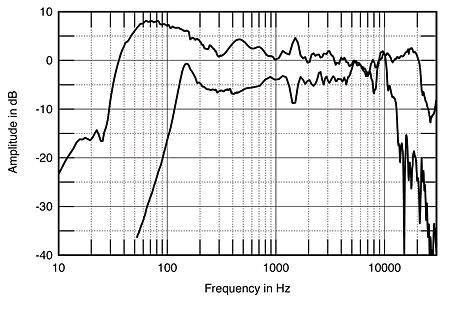
Fig.4 Mirage M-7si, anechoic response on tweeter axis at 52" averaged across 30° horizontal window and corrected for microphone response, with complex sum of nearfield woofer and port responses below 300Hz. The rear drive-unit response is also shown, plotted 4dB too low, for clarity.
There's a troubling peak at about 1.5kHz, and a smaller dip at 7kHz; both are related to woofer-breakup modes visible in fig.3. Both are also relatively narrow (the peak at 1.5kHz covers about 1/3 of an octave), and didn't cause problems in the listening tests. Nevertheless, curing them offers an opportunity for possible future improvements to the design. Aside from these two problem areas, the response is relatively smooth and flat above 1kHz, as expected from the auditioning
The response of the rear driver in fig.4 is relatively flat in its passband, and extends to 10kHz and 150Hz, where there are sharp peaks with rapid rolloffs beyond. (For clarity, the response of this driver has been plotted about 4dB too low in level.)
The horizontal response family of the Mirage M-7si, with any on-axis response deviations subtracted so that the on-axis response appears as flat, is shown in fig.5. There's an off-axis notch in the upper midrange (just below 1kHz), perhaps caused by cancellation between the front woofer and the rear MSE. The woofer has good dispersion up to the top of its response; no notch is visible off-axis at the 1.8kHz crossover frequency. There's a noticeable rolloff in the treble response off-axis. From the looks of the vertical-response plot (fig.6), the vertical listening angle appears to be quite critical. You should not listen to the M-7si more than a few degrees above or below the tweeter axis if you wish to avoid a suckout at the crossover frequency.
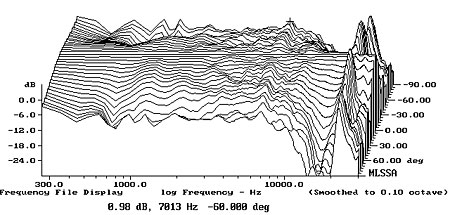
Fig.5 Mirage M-7si, horizontal response family at 52", normalized to response on tweeter axis, from back to front: differences in response 90°–5° off-axis; reference response; differences in response 5°–90° off-axis.
Fig.6 Mirage M-7si, vertical response family at 52", normalized to response on tweeter axis, from back to front: differences in response 60°–5° above tweeter axis; reference response; differences in response 5°–30° below tweeter axis.
The impulse response on the tweeter axis, shown in fig.7, is respectable, though not exceptional. Note, however, that the metal-dome tweeter is relatively free of ultrasonic ringing. The step response in fig.8 indicates that the two main drivers are connected in-phase, with the woofer response about 1 millisecond behind the tweeter—not time-aligned, but not far off either. The tweeter appears to be balanced to a lower output level than the woofer. The small wrinkle at about 7.7ms is a room reflection. The step response of the rear drive-unit is shown in fig.9. Surprisingly, this appears to be connected with negative polarity. (Both samples measured were the same in this respect.)
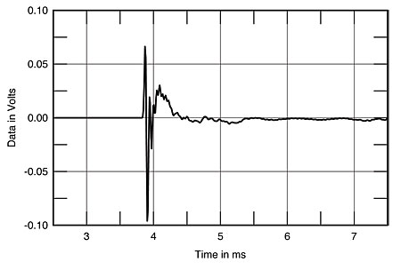
Fig.7 Mirage M-7si, impulse response on tweeter axis at 52" (5ms time window, 30kHz bandwidth).
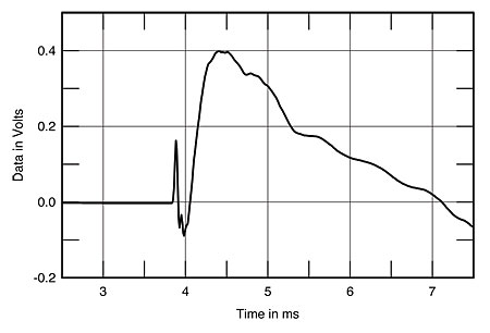
Fig.8 Mirage M-7si, step response on tweeter axis at 52" (5ms time window, 30kHz bandwidth).
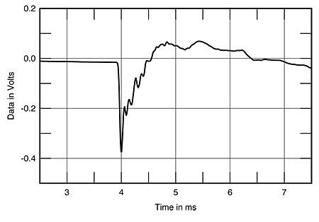
Fig.9 Mirage M-7si, rear drive-unit step response at 52" (5ms time window, 30kHz bandwidth).
In a bipole design, the rear driver should be connected with the same polarity as the front drivers. When fed a DC pulse, both then move outward, away from their respective speaker baffles. As they are mounted facing in opposite directions, their cones therefore move in the opposite direction from each other. With the rear driver connected as shown in fig.9, however, a DC pulse will result in front and rear cones moving in the same direction, which is the mark of a dipole design. Perhaps the review samples were incorrectly wired: I assume that Mirage will address this matter in their "Manufacturer's Comment."
The cumulative spectral-decay, or waterfall, plot is shown in fig.10. The only notable feature is the woofer mode at 1.5kHz. The treble is particularly clean, with noticeably less hash than is commonly observed. (The ridge just above 15kHz is not due to the loudspeaker—it comes from the computer monitor used in the measurements.)
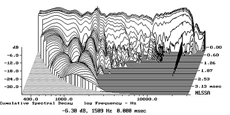
Fig.10 Mirage M-7si, cumulative spectral-decay plot at 45" (0.15ms risetime).
This is a solid set of measurements for a loudspeaker in this price range. I would like to see less of a mid- to upper-bass rise (provided that doesn't compromise the otherwise admirable bass extension or lean-out the sound too much), and a smoother rolloff with fewer breakup modes at the top end of the woofer's response. This is already a very good loudspeaker—with a few refinements, it could be a giant-killer.—Thomas J. Norton
|
| ||||||||||
- Log in or register to post comments


| Loudspeakers Amplification Digital Sources | Analog Sources Accessories Featured | Music Columns Retired Columns | Show Reports | Features Latest News Community | Resources Subscriptions |
 © 2024 Stereophile
AVTech Media Americas Inc., USA
All rights reserved

