| Columns Retired Columns & Blogs |
... Bob Stuart's engineering expertise?
If so, maybe you'd rather get the player that JGH would have bought:
https://www.stereophile.com/content/sony-cdp-x779es-cd-player-page-2
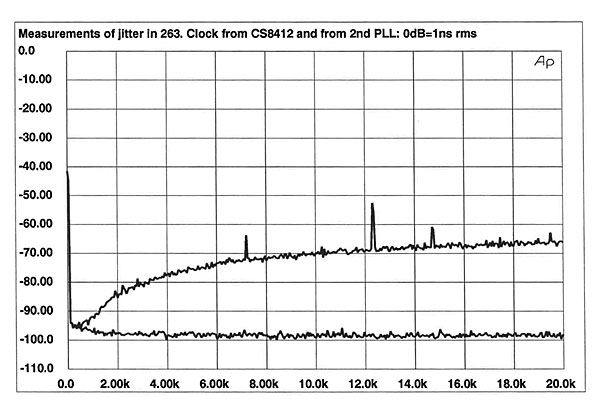
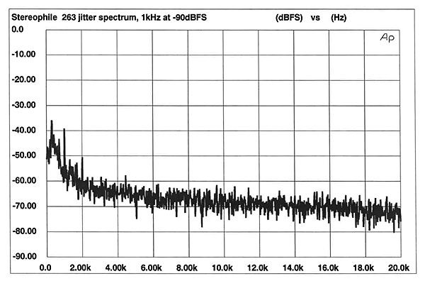
The 263's output when driven by a full-scale (0dBFS) 1kHz digital input signal was 2.2V. Channel balance was excellent, with channel matching of 0.07dB. Output impedance measured a low 46 ohms across the band. DC offset levels were minimal, measuring 1.3mV (left channel) and 0.7mV (right channel). The 263 had no problem locking to 32kHz and 48kHz sampling rates, although as noted in the technical description, the double lock feature didn't engage at those input frequencies. Bob Stuart made clock-jitter measurements (using an FM demodulator, similar to the Meitner LIM Detector technique) with and without the second PLL. Bob's measured results are shown in fig.1. The vastly lower jitter with the second PLL (lower trace) and absence of discrete-frequency jitter components is readily apparent. (The input signal to the 263 during these measurements wasn't specified.)
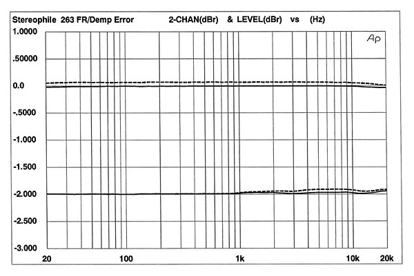
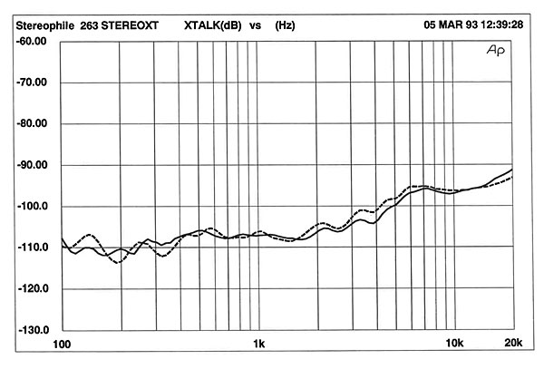
The 263 doesn't invert polarity. Frequency response, shown in the upper trace of fig.2, was perfectly flat, with virtually no rolloff at 20kHz. De-emphasis error (bottom trace of fig.2) was negligible, particularly considering that de-emphasis is performed in the analog domain and subject to component tolerances. Fig.3 shows the 263's excellent channel separation, which measured 107dB at 1kHz. Even at 20kHz, channel separation was better than 90dB. This is superb. The unusual bump in the crosstalk measurement centered at 7kHz may be noise or an idle tone of some kind: It corresponds exactly to a similar rise in the noise floor seen in the noise modulation plot shown later.
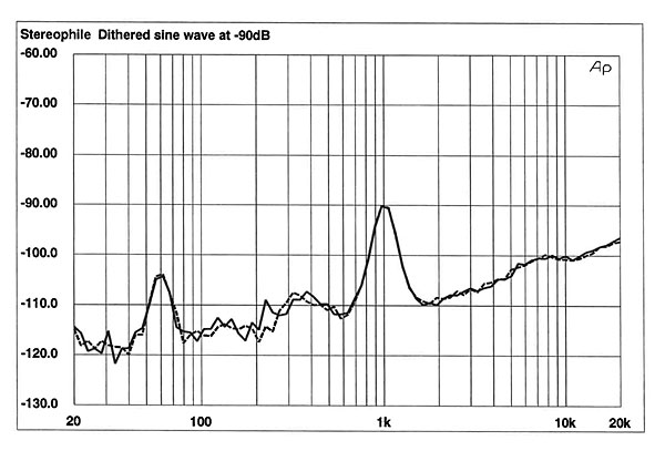
A 1/3-octave spectral analysis of the 263's output when decoding a –90dB, dithered 1kHz sinewave is shown in fig.4. There is a relatively high level of 60Hz AC noise, though this is still more than 100dB down from full modulation. Note, however, the good linearity (the signal peaks exactly at the $*–90dB horizontal division) and matched performance of the DAC's two channels (seen as overlapping left- and right-channel traces at the test-signal frequency).
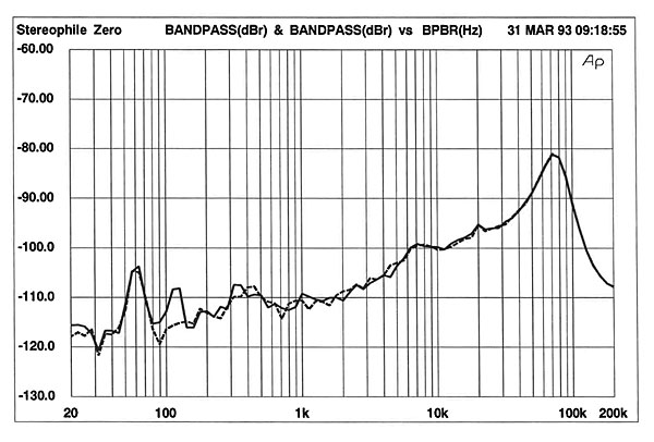
The same type of analysis, but this time with the 263 driven by digital silence (all data words zero) and a wider measurement bandwidth, is shown in fig.5. Note the rapid noise-floor rise above 20kHz due to the noise shaping used in the CS4328. There are also slight rises in the noise floor centered at 400Hz and 7kHz. I'll take a closer look at this in the noise modulation plot.
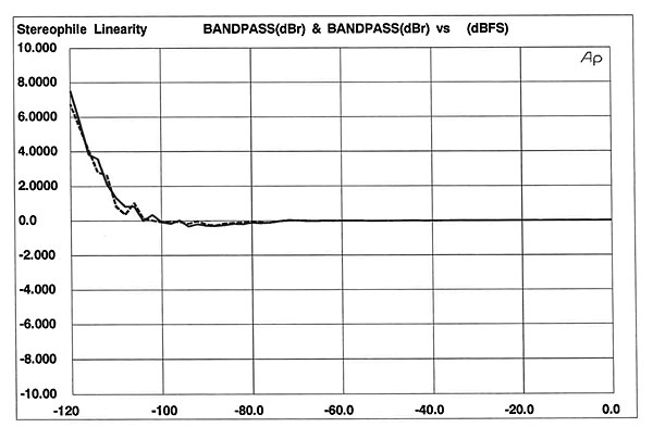
When I measured the 263's low-level linearity using the standard test, it appeared to have severe negative linearity errors below –80dB. I questioned this result for several reasons: The Crystal databook shows the CS4328 to have excellent linearity; 1-bit DACs excel in this area; and the –90dB peak in fig.4 exactly reached the –90dB horizontal division—indicating that the analog output was indeed at –90dB. Bob Stuart suggested that I repeat the measurement at a 48kHz sampling frequency (instead of 44.1kHz). Here's why: As the Audio Precision's signal generator drops in level to make the linearity measurement, its output glitches. This causes the 263's second, narrow-window PLL to lose lock momentarily. As it loses lock, the DAC's output level drops, then comes back to normal after the first PLL is switched in. This proved to be the case: At 48kHz, the 263 had excellent linearity, shown in fig.6. The DAC is virtually perfect to –105dB, and both channels exhibit identical behavior. Note that this will not be a factor in normal listening; CD transports put out a continuous S/PDIF signal.
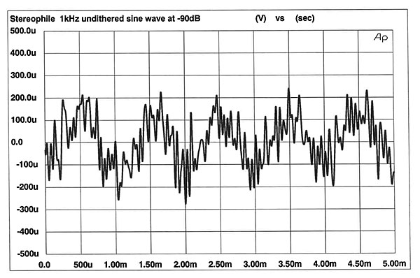
Capturing an undithered, –90dB, 1kHz sinewave produced the waveform of fig.7. The signal is overlaid with audioband noise—see fig.7 in the Sony review elsewhere in this issue for an excellent low-noise waveshape—but the 263's waveform symmetry is good.
The noise-modulation plot (fig.8) was unusual in that the noise floor had an unusual spectrum, with distinct peaks at 500Hz and 7kHz. These were hinted at in figs.4 and 5. I've never seen a noise spectrum shaped like this. Perhaps Meridian can address this in their "Manufacturer's Comment." Of most importance, however, is that the five traces are closely grouped and don't cross each other. In this regard, the 263 was excellent; the processor's noise floor, and the spectral content of that noise, varies very little as a function of input level.
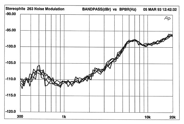
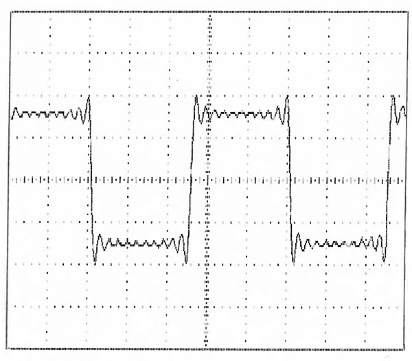
Fig.9 shows the 263's reproduction of a full-scale, 1kHz squarewave. The shape is typical of linear-phase digital filters, but there is more overshoot than seen with the NPC digital filters.
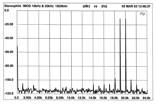
Performing an FFT on the 263's output when the unit was decoding a full-scale mix of 19kHz and 20kHz sinewaves produced the plot of fig.10. The 1kHz difference component (20kHz minus 19kHz) can be seen, but is very low in amplitude. Other than minor spikes at 14kHz, 16kHz, 17kHz, 18kHz, and 21kHz, the intermodulation spectrum is quite clean.
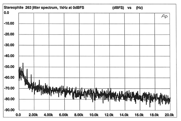
I next looked at the 263's audioband jitter spectrum by feeding the 256x clock (11.2896MHz) at the CS4328 DAC into the Meitner LIM Detector. An FFT was performed on the LIM Detector output, with varying data input levels to the 263. The resulting spectra, normalized to an 8x-oversampling clock (see April '93, p.257), are shown in figs.11 and 12. Fig.11 was taken with a full-scale, 1kHz sinewave input signal (best case), fig.12 with a –90dBFS, 1kHz sinewave input signal (worst case). The RMS level at full scale was an astonishingly low 45 picoseconds (again normalized to the 8fs clock frequency). The worst case was 75ps, meaning that the 263 had the lowest measured jitter of any I've tested. Moreover, the spectra are nearly perfectly clean; there are no periodic jitter components that would appear as spikes in the plot. There are two signal-correlated components (at 1kHz in fig.11 and at 1kHz and 2kHz in fig.12), but they are low in amplitude, and the rest of the spectrum is perfectly clean. Overall, this is exemplary performance, and, along with the Meitner IDAT, the best I've measured. It is perhaps no coincidence that the two designers who devised their own jitter measurement methods (Ed Meitner and Bob Stuart) produced processors with the lowest audioband jitter. The 263's dual PLL, and careful handling of the clock, no doubt account for this extraordinary performance.
Since we published the article on jitter in January's Stereophile, the Meitner LIM Detector has been significantly revised. The readings it provides no longer need to be scaled to the clock frequency. Moreover, its intrinsic noise floor has been lowered, and it has one output derived from an FM detector (as with the original) and another output derived from a true phase detector. The difference is a 6dB/octave change in the jitter's plotted spectral tilt. There are arguments for both methods of presenting the data. I should also point out that the LIM Detector only looks at audioband jitter (20kHz bandwidth), while jitter up to 40kHz can produce audible degradation. It is possible, though highly unlikely, that a clean-looking spectrum could be very poor above 20kHz and a spiky spectrum very clean above 20kHz. I think, however, that in general, the audioband spectrum is representative of sonically significant jitter.
There are several mechanisms that could account for the slightly different jitter spectra shown in figs.10 and 1, the jitter spectrum measured by Meridian. These include: the probe's loading effect on the word clock; where the probe was grounded; the different test instruments' intrinsic noise floors and spectral distributions of that noise; and use of different jitter measurement techniques. Note also that the Meridian data are referenced to a 1ns 0dB reference; we use a 226.8ns reference, which is 1% of the 44.1kHz sampling period, and normalize the jitter to an 8fs clock frequency. Despite the difference in absolute levels, there is a correlation between the results in that neither test instrument shows the presence of high-amplitude periodic jitter components.
Finally, I used the Pierre Verany Test Disc to check the 200's error-correction and tracking abilities. One section of the disc has dropouts in the CD's spiral data track which increase in length. By listening to the tone and noting at which track the tone is interrupted, you can get a good idea of how well the machine tracks. The higher the track number without mistracking, the better. The 200 played perfectly until track 33, but glitched on track 34. This is typical performance.
I had an interesting experience with the 200's error-correction abilities. A reader at the Stereophile High-End Hi-Fi Show in San Francisco lent me some discs he thought I'd like, based on music I've written about. One of the discs, Go Between by The New Percussion Group of Amsterdam (with special guest Bill Bruford), produced a large amount of distortion that was correlated with the music when played in the 200. When played on the Mark Levinson No.31, however, the distortion was still apparent, but at a lower level (footnote 1).—Robert Harley
|
| ||||||||||

... Bob Stuart's engineering expertise?
If so, maybe you'd rather get the player that JGH would have bought:
https://www.stereophile.com/content/sony-cdp-x779es-cd-player-page-2

Meridian gear has always been over priced and under performing.


| Loudspeakers Amplification Digital Sources | Analog Sources Accessories Featured | Music Columns Retired Columns | Show Reports | Features Latest News Community | Resources Subscriptions |
 © 2024 Stereophile