| Columns Retired Columns & Blogs |
Magico V3 loudspeaker Measurements
Sidebar 3: Measurements
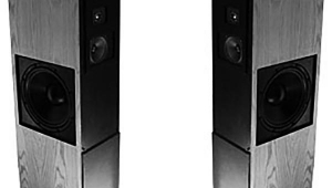
My estimate of the Magico V3's voltage sensitivity was 87dB(B)/2.83V/m, slightly lower than specified. The speaker's impedance (fig.1) remained below 4 ohms for much of the audioband, with minimum values of 3 ohms at 97Hz and 2.7 ohms at 7kHz. There is also a combination of 4 ohms and a –50° capacitive phase angle at 4kHz. Overall, the V3 is a demanding load that should be partnered with amplifiers that have no problem delivering high currents.
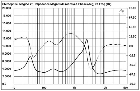
Fig.1 Magico V3, electrical impedance (solid) and phase (dashed). (2 ohms/vertical div.)
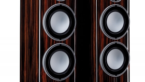
The traces in fig.1 are free from the small wrinkles due to the presence of cabinet panel resonances; when I investigated the enclosure's vibrational behavior with an accelerometer, I could find no resonant modes. When I listened to the panels with a stethoscope while playing the stepped toneburst track on my Editor's Choice CD (Stereophile STPH016-2), the front baffle was inert, as were the side panels. However, a small section of the rear panel immediately behind the midrange unit was quite lively between 375 and 550Hz (fig.2). The facts that the area affected is small and faces away from the listener will mitigate any audible consequences of this behavior.
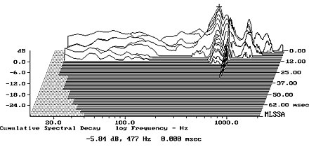
Fig.2 Magico V3, cumulative spectral-decay plot calculated from the output of an accelerometer fastened to the center of the rear panel (MLS driving voltage to speaker, 7.55V; measurement bandwidth, 2kHz).
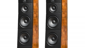
The peak centered at 33Hz in the impedance-magnitude trace suggests that this is the tuning frequency of the twin woofers, equivalent to the frequency at which the speaker's anechoic response will be down 6dB. This is confirmed by the sum of the woofers' nearfield responses measured with DRA Labs' MLSSA system (fig.3, red trace; the two woofers behaved identically). Peculiarly, the woofers had a small peak evident at 105Hz, before beginning what appears to be a smooth second-order rolloff to hand over to the midrange unit above 180Hz (fig.3, blue). Both the woofers' and the midrange unit's low-pass rolloffs also appear to be second-order. The black trace below 300Hz in this graph shows the complex sum of the nearfield woofer and midrange output; above 300Hz, it shows the V3's farfield response averaged across a 30° horizontal window on the tweeter axis. Good frequency-domain integration of the lower-frequency drive-units' outputs is evident, though a slight lack of on-axis energy can be seen between 3 and 5kHz, with the tweeter then balanced a couple of dB too high in level.
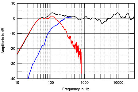
Fig.3 Magico V3, anechoic response on listening axis at 50", averaged across 30° horizontal window and corrected for microphone response, with the nearfield responses of the midrange unit (blue) and woofers (red), plotted in the ratios of the square roots of their radiating areas below 800Hz and 400Hz, respectively, and the complex sum of the nearfield responses plotted below 300Hz.
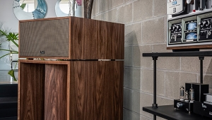
It is possible that this lack of energy correlates with the rather polite balance I occasionally noted in my auditioning, but the V3's dispersion also needs to be taken into account. In fact, the plot of the V3's lateral radiation pattern (fig.4) shows that this on-axis suckout does tend to fill in to the speaker's sides. In rooms of small to medium size, the V3 will sound more neutrally balanced, though the lack of off-axis output to its sides at the top of the midrange unit's passband is what makes the speaker's sound rather laid-back in character. I suspect that this laid-back character is a result of the slight recessing of the midrange unit into the front baffle. The ring-radiator tweeter, however, maintains its off-axis output to a higher frequency than I have seen from other versions of this drive-unit.

Fig.4 Magico V3, lateral response family at 50", normalized to response on tweeter axis, from back to front: differences in response 90–5° off axis, reference response, differences in response 5–90° off axis.
In the vertical plane (fig.5), the V3 maintains its balance over a quite wide (+5°, –10°) window centered on the tweeter axis, which is 39" from the floor when the speaker is supported by its carpet-piercing spikes. The sharp notch at 2.7kHz apparent in the speaker's output more than 10° above the tweeter axis suggests that this is the crossover point between the two upper-frequency drivers.
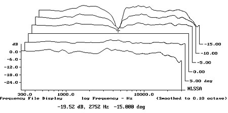
Fig.5 Magico V3, vertical response family at 50", normalized to response on tweeter axis, from back to front: differences in response 15–5° above axis, reference response, differences in response 5–10° below axis.
To look at how this quasi-anechoic behavior translates into the speakers' behavior in the listening room, I took ten 1/6-octave–smoothed spectra for each speaker individually in a rectangular grid 40" wide by 18" high and centered on the position of my ears in my listening chair. (I used an Earthworks omni microphone and a Metric Halo ULN-2 FireWire audio interface, in conjunction with SMUGSoftware's Fuzzmeasure 2.0 running on my Apple laptop.) This spatial averaging minimizes the effects of room acoustics on the measured response. The result for the Magico V3 is generally even (fig.6). There are still some room effects visible below 400Hz, but the reinforcement of the low frequencies by the room boundaries results in bass extension that is flat all the way down to 20Hz! There is a visible depression in the low-treble region; whether this results in a polite character or whether the slight excess of energy between 4 and 10kHz gives a slightly bright balance will depend on the music being played and which region the ear takes as its "anchor."
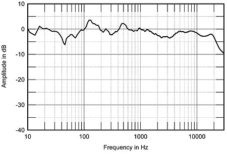
Fig.6 Magico V3, spatially averaged, 1/6-octave response in JA's listening room.
Turning to the time domain, the V3's step response (fig.7) indicates that while the tweeter and midrange unit are connected with positive acoustic polarity, the woofers are connected in inverted polarity. (I confirmed this by looking at the step responses of the individual units, not shown.) This opposite-polarity connection is to be expected, given the use of a second-order crossover for the lower-frequency units, as it counteracts the phase shift that results from the crossover filters. The negative-going step of the woofers in this graph is smoothly integrated with the negative-going overshoot of the midrange unit's step, this correlating with the good frequency-domain integration of their outputs seen in fig.3.
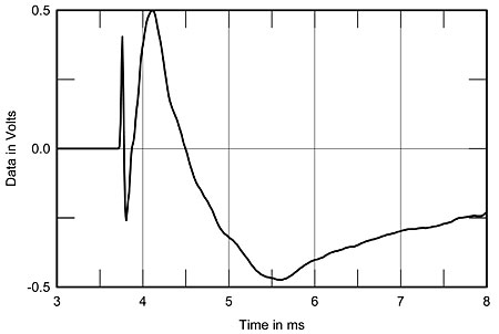
Fig.7 Magico V3, step response on tweeter axis at 50" (5ms time window, 30kHz bandwidth).
Finally, the V3's cumulative spectral-decay plot (fig.8) is superbly clean in the region covered by the tweeter, although a slight amount of delayed energy can be seen associated with the small on-axis peak at 2.7kHz. Nevertheless, I heard no hardness that might be associated with this behavior.— John Atkinson
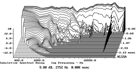
Fig.8 Magico V3, cumulative spectral-decay plot on tweeter axis at 50" (0.15ms risetime).
|
|
| ||||||||||
- Log in or register to post comments


| Loudspeakers Amplification Digital Sources | Analog Sources Accessories Featured | Music Columns Retired Columns | Show Reports | Features Latest News Community | Resources Subscriptions |
 © 2024 Stereophile
AVTech Media Americas Inc., USA
All rights reserved

