| Columns Retired Columns & Blogs |
What a brilliant article! Really enjoyed the Feb edition as well as this one.
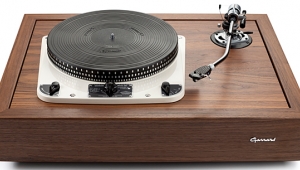
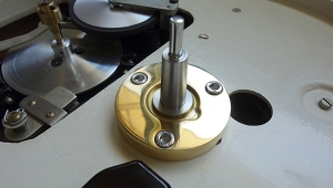
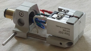
Let's also pause for a word about tonearms: Because they're best suited for the low-compliance pickup heads that sound best with high-torque turntables, and because they neither require antiskating connivances nor exhibit much in the way of tracking-error distortion when installed correctly, I vastly prefer old-style transcription-length (ca 12") tonearms to their shorter (ca 9") counterparts. You may not own such an arm today, but you might acquire one in the future; for that reason, I suggest thinking big and opting for a plinth a full 22" wide by 17" deep. According to the formulas described by Keith Howard in, appropriately enough, Stereophile's Vol.33 No.3 (March 2010; see "Arc Angles" on p.51), my EMT 997 tonearm requires a spindle-to-pivot distance of 294.58mm for an A-style pickup head, and 316.325mm for a G-style pickup head—both of which dimensions are easily accommodated in this plinth design (footnote 1).
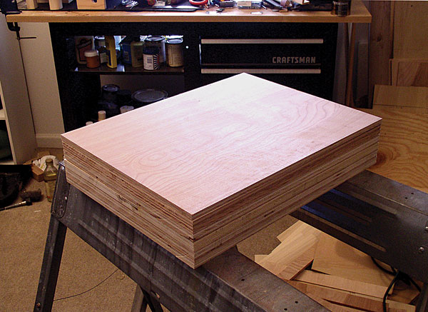
So it was that the first step in building my plinth was nothing more or less than clamping sheets of plywood to my sawhorses, sometimes two or even three at a time; then measuring and marking them with painstaking care, and trimming them to size with a circular saw. I then rough-sanded the boards to match each other within a fraction of an inch—not only to cut down on my finish work later on, but for the precision required to use each completed sheet as a template for the next layer down.
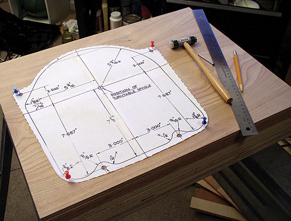
The next step was less brutal, requiring only a computer and a printer/scanner: I scanned in the mounting template from my Garrard 301 owner's manual (one could download the same thing from various online sources, including www.vinylengine.com), then used Adobe Photoshop to divide the image into quadrants, after which I resized and printed the quadrants by trial and error, in order to assemble a full-size template. (Sample dimensions noted on the Garrard original template make it easy to check and confirm accuracy.) I selected the prettiest of my ½" plywood sheets, lined up the template, held it in place with pushpins, and used a punch and a hobbyist's knife to trace the drill points and outline.
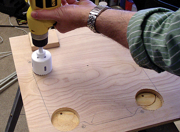
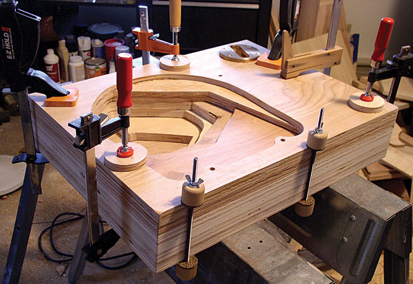
I then clamped a thick sheet of scrap plywood (to prevent splinters) under the top board, and used the two hole saws to create a total of five moderately large openings on the top: the 2¾" holes that define the left and right front corners of the cutout; a third 2¾" hole that defines a bend in the left-hand edge of the outline; and a pair of 2" holes that nearly complete the front edge of the cutout. After that, I drilled the four 5/16" holes for the Garrard 301's mounting bolts, and marked and drilled the final location of my tonearm mount.
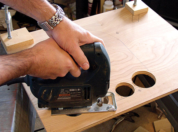
Next, I removed the plywood scrap, reclamped my top sheet, and used the jigsaw to finish cutting the outline. Yee-haw! This was beginning to look like a real, store-bought plinth!
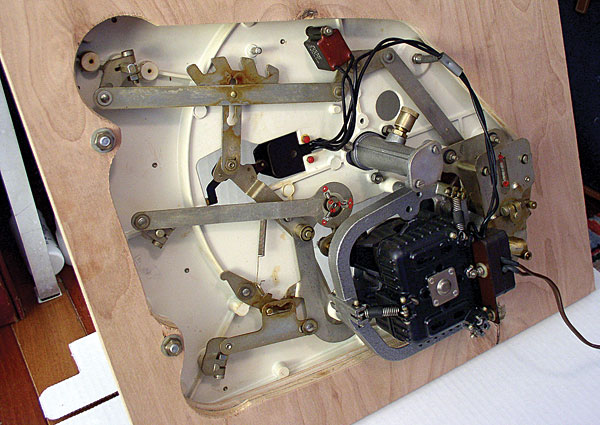
After that, I test-fitted my 301 to the top sheet—happily, the mounting bolts lined up perfectly with the holes I'd made for them—and applied a straightedge from underneath to determine whether the entire cutout needed to be repeated on the next sheet down, to clear all the mechanicals. It turned out that I could eliminate a considerable portion of the cutout for layer No.2, the border points of which I marked off on the cutout of layer 1 before using it as a template.
So it went, from one sheet to the next. The cutout in layer 3 was smaller than that for layer 2, the cutout for layer 4 was smaller than the one for layer 3, and so forth. But there were some key distinctions:
• Only in the top two layers did I drill 5/16" holes for the mounting bolts. For every subsequent (lower) layer I used the ¾" Forstner bit, which provided just enough room to apply washers and nuts from underneath, and to tighten them with an appropriate nut driver.
• In layers 3 and 4 I had to drill a hole near the front-right corner of the motor-unit cutout, to accommodate some kind of mechanical doodad. I more or less guessed at the hole's precise location, and luckily I got it right—aided by the fact that I'd drilled a ¾" hole when a ¼" hole would have sufficed.
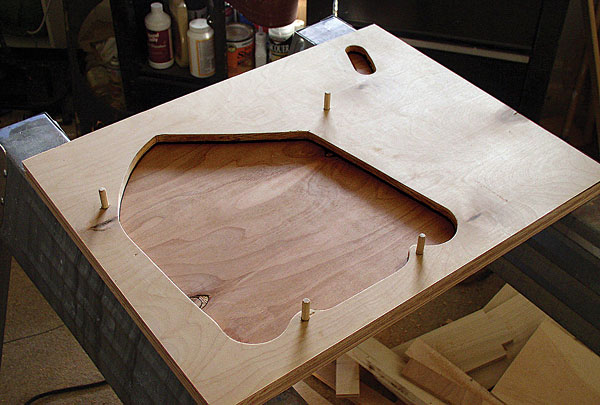
• In layer 4 I cut an oblong channel from my tonearm cutout to the rear edge of the plinth, for the signal wires. In layer 6 I created a larger version of the same thing, from the left-hand side of the motor-unit cutout to the rear edge of the plinth, for the motor unit's AC cord.
• Apart from the four 1" holes for access to the mounting nuts, I left layer 7 entirely solid.
Next came the gluing, which was almost as straightforward as you might have guessed. I began by joining layers 1 and 2, keeping them aligned by pushing 5/16" wooden dowels through the holes I'd made for the mounting bolts, and adding one layer at a time, each layer added only after the previous bond had dried overnight.
|
| |||||||||

What a brilliant article! Really enjoyed the Feb edition as well as this one.
Seeing the concept of a plinth broken down like that; or rather seeing it constructed like that... I feel like I've been reading/viewing post-grad philosophy material.
Outstanding stuff; and big kudos for doing the work yourself... so few can actually craft anymore.
Awesome!
What a fascinating project, very well executed!
I had a 301 in the 70s, when I was a budget-constrained student. I paid £10 for it!
My plinth was a single piece of plywood, supported by a fiberglass base. I had a summer job in a fiberglass factory, so that part was easy enough to have manufactured at zero cost to me.
Yes, it rumbled! But what I discovered was that the rumble was coming from mechanical transmission through the plinth to the tone-arm. I solved it by removing the turntable-to-plinth bolts, and instead resting the turntable on foam pads. The foam I used was the type used for bicycle handlebar padding (I happened to have some offcuts). Pipe lagging foam has a similar density, and would probably also work.
In addition I used the fairly well-known trick of wiring a light bulb in series with the motor, to reduce the motor torque. Experimentation is required, but I think I ended up with a 60W tungsten light bulb.
With these two fixes in place, the rumble was cured.
Stupidly, I got rid of the turntable about 20 years ago, when it seemed that vinyl was dead. What a fool! I wish I could have it back, but I doubt I’ll find another for £10.


| Loudspeakers Amplification Digital Sources | Analog Sources Accessories Featured | Music Columns Retired Columns | Show Reports | Features Latest News Community | Resources Subscriptions |
 © 2024 Stereophile