| Columns Retired Columns & Blogs |
Erin's Audio Corner just measured these too. Amazing. Measures better than the JBL M2
Because of the JBL 4367's size and weight, I drove my gear—DRA Labs' MLSSA system, an Earthworks microphone preamplifier, calibrated DPA 4006 and Earthworks QTC-40 microphones, and Dayton Audio's DATS V2 system—to AH's apartment for the measurements. While we were able to lift one of the speakers onto a short stack of 2 × 4s sitting on top of a dolly for the testing, the woofer was still relatively close to the floor. Reflections from the floor will therefore reduce the midrange resolution of the farfield response measurements. During these measurements, the speakers were driven by an Ayre Acoustics AX-5 Twenty amplifier. All measurements were made with the HF control in its center, neutral position.
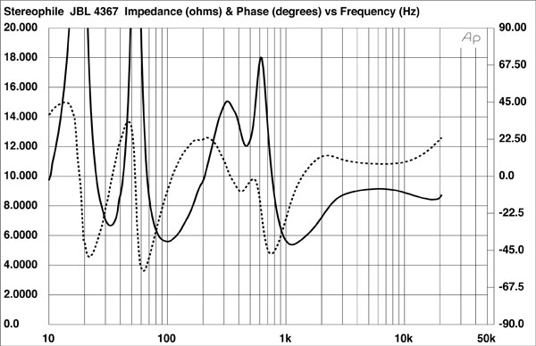
JBL specifies the 4367's sensitivity as 94dB/2.83V/m. My B-weighted estimate was slightly lower, at 92.7dB(B)/2.83V/m, but this is still a loudspeaker that will play at high levels with only a few watts. The JBL 4367's impedance is specified as 6 ohms. Measured with the DATS V2, the impedance magnitude (fig.1, solid trace) remained above 6 ohms for almost the entire audioband. The minimum magnitude was 5.6 ohms at 96Hz and 5.4 ohms between 1080Hz and 1180Hz. The electrical phase angle (dashed trace) is high in a couple of regions, however, and the equivalent peak dissipation resistance, or EPDR (footnote 1), drops to 2.5 ohms between 70Hz and 80Hz and 2.4 ohms between 885Hz and 950Hz. The JBL 4367 will work best with amplifiers that are not fazed by 4 ohm loads, but the need for current will be alleviated by the JBL's high sensitivity.
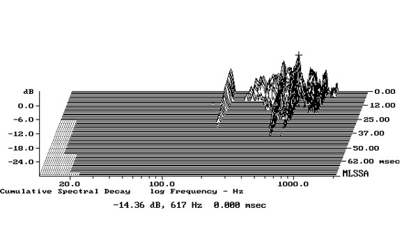
I investigated the enclosure's vibrational behavior with a plastic-tape accelerometer. Despite the large size of the panels, they were relatively quiet, and the only resonant modes were low in level. Fig.2 is a cumulative spectral-decay plot calculated from the accelerometer's output when it was fastened to the center of one of the sidewalls, level with the woofer. The highest-level mode, at 617Hz, is still low in absolute terms.
The saddle centered on 31Hz in the impedance magnitude trace suggests that this is the tuning frequency of the twin ports on the front baffle, which implies extended low frequencies. The red trace in fig.3 shows the port's nearfield output. The response peaks a little higher than the tuning frequency, and while the upper-frequency rolloff is initially clean, some low-level peaks are visible in the midrange. The nearfield response of the woofer (fig.3, blue trace below 350Hz) has the expected notch at the ports' tuning frequency, which is when the back pressure from the port resonance holds the diaphragm stationary. The 5dB peak in the upper bass is due entirely to the nearfield measurement technique, which assumes the drive-unit is mounted in a true infinite baffle, ie, one that extends to infinity in both planes.
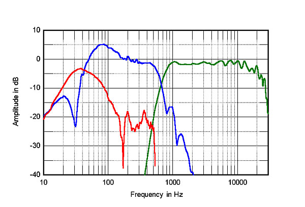
The blue trace above 350Hz in fig.3 shows the woofer's farfield output, measured on the tweeter axis. It crosses over to the horn-loaded midrange/tweeter (green trace) close to the specified 700Hz with what appear to be symmetrical third-order filter slopes. Some response irregularities can be seen in the top two audio octaves, probably due to reflections of the horn-loaded tweeter's output from the mouth of the horn.
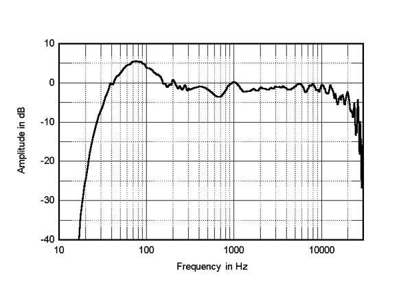
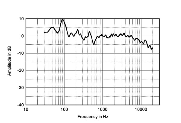
In fig.4, the black trace below 300Hz shows the complex sum of the nearfield woofer and port responses taking into account acoustic phase. The upper-bass boost in the loudspeaker's low frequencies will again be due to the nearfield measurement technique; the 4367's low frequencies appear tuned to be maximally flat, in textbook manner. Higher in frequency, in fig.4, the JBL's farfield response, averaged across a 30° horizontal window centered on the tweeter axis, is impressively even, except for a small dip and subsequent peak between 500Hz and 1kHz and the top-octave irregularities mentioned earlier.
The 4367's horizontal dispersion is shown in fig.5. (The traces are normalized to the response on the tweeter axis, which thus appears as a straight line.) Other than a slight lack of energy to the sides in the crossover region and some small peaks and dips in the top audio octave, the contour lines in this graph are smooth and even. The JBL's vertical dispersion, again normalized to the response on the tweeter axis, is shown in fig.6. The JBL 4367's tweeter axis is 32" from the floor, lower than the average ear height for seated listeners, which a 1990s survey for Stereophile indicated was 36". Fig.6 indicates that the response 5° above the tweeter axis is basically identical, so there should be no problem for seated listeners. Higher than that, however, a suckout starts to appear in the crossover region.
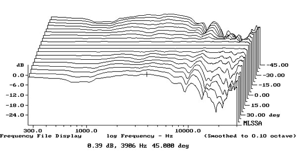

Fig.7 shows the JBL 4367's spatially averaged response in AH's room. To generate this graph, I average 20 1/10-octave– smoothed responses taken individually for the left and right speakers in a vertical rectangular window centered on the position of the listener's ears. Averaging tends to minimize the effect of room resonances on the measured response below 400Hz. Other than a peak in the upper bass, which might have been due to the fact that the speakers were placed relatively close to the wall behind them, and a lack of energy just below the crossover region, the JBL's in-room response is impressively flat through the mid-treble region, above which the usual gentle slope down with increasing frequency is present.
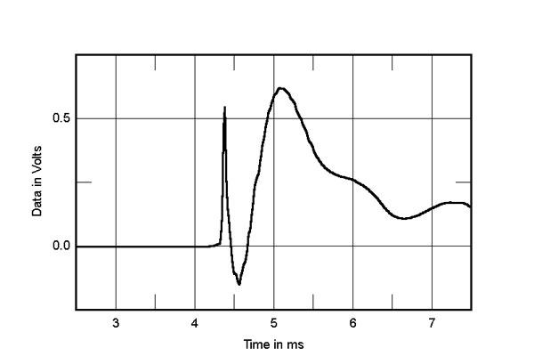
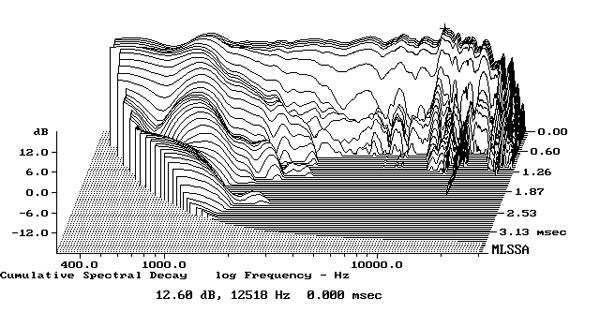
In the time domain, the JBL 4367's step response on the tweeter axis (fig.8) indicates that both drivers are connected in positive acoustic polarity and that the upper-frequency driver's output arrives first at the microphone. The decay of this unit's step smoothly blends with the start of the woofer's step, suggesting optimal crossover design. The ripples in the response after 5.5ms might be due to reflections of the woofer's output from the floor. The JBL's cumulative spectral-decay plot (fig.9) has a ridge of delayed energy around 1kHz. This graph is otherwise superbly clean in almost all of the region covered by the horn-loaded drive-unit.
I wasn't sure what to expect from the 4367's measurements. My experience in the 1970s of high-sensitivity designs with horn-loaded drive-units led me to believe that too many compromises are needed to achieve such high sensitivity. No such compromises were made with the JBL 4367 Studio Monitor—it offers textbook measured performance.—John Atkinson
|
| ||||||||||


Super piece! I love your thoughts on dynamics and ability to startle. I prefer high end contemporary gear, but too often I've looked forward to being blown away by the latest offering from a highly respected manufacturer, only to wonder why anyone would drop $20 or 50K on speakers that just left me cold--like I had been to a laboratory rather than a concert
The new Pilium Audio gear could be a great match with these JBL speakers

Impressively smooth for a horn system.
I imagine some La Scalas, Cornwalls, or Klipschorns will get you even closer to your Altecs than the JBLs did.

Hi
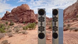
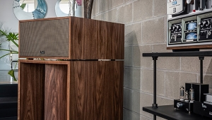
Is the picture above showing yr home system driving the JBL ?
Jack L

... that the image was either provided by JBL or taken directly from their website: https://www.jbl.com/floorstanding/Studio+Monitor+4367.html?dwvar_Studio%20Monitor%204367_color=Black-China-Current&cgid=Floorstanding
Hi
What a de-saling picture presentation !
If so, either those involved in making this image were photograhers, without enough knowlege of loudspeaker acoustics!
How can a floorstanding loudspeakers be placed so close against the corner wall & sandwished between the tall equipment cabinet & unshaded glass partition ?????
How could such loudspeaker placement be acceptable to JBL let alone we consumers ?
Listening is believing
Jack L
Six feet apart is absolutely ridiculous. JBL’s shouldn’t be taken at “face value” (initiate capacity) but set to work in a diffused manner. Corroborating both “diffused” speakers lends to a sound field of substantial enormity. I seriously doubt such proximate placement can tap into this character.
A great review of a great set of speakers.
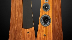
It's a shame that the technologies implemented in the driver designs were glossed-over so casually. The Dual Differential Drive configuration has tangible performance benefits.
Readers would be well-served to read JBL's white paper on these speakers to gain a better understanding of how transducer technology improves the accuracy of the listening experience.
https://www.jbl.com/on/demandware.static/-/Sites-masterCatalog_Harman/default/dwe983f9a9/pdfs/JBL%204367%20White%20Paper.pdf
Impressive measurements. Reading the white paper, it is cool to see the old JBL tech from the 70's using DC bias on capacitors.
One thing that bothers me is the stored energy around 1kHz, right around B natural. That is a really terrible place to have a resonance. Perhaps it was not too audible? [ed.] A 15" woofer will begin to beam at 900 Hz, which would limit audibility.
A simple notch filter could probably deal with it, though. Strange choice not to implement that.
Hi
"The networks also employ DC voltage bias to operate
the capacitors effectively in a Class A mode" quoted JBL white paper.
WHY need to DC bias to "classs A mode" for a polypropylene cap ?????
Pardon me for being so technically ignorant ! This is not an audio amp where the active devices, e.g. tube or transistor, which work on DC bias voltage to be able to operate at Class A, B or AB......
But a loudspeaker passive x-over network is NOT an amp !!!!!!
FYI, I've DIY upgraded the 2-way x-over network of my KEF standspeakers
by modifying it bi-wiring (for much better sound) & replacing all the lousy polar electrolytic caps to large non-polar metallized polypropylene film caps 2 decades back. NOOOO need any DC biasing at all.
The upgraded bi-wired KEF sound sooooo much more detailled & smooth for the entire audio spectrum. Working like a chime !!
Would some loudspeakers experts chime in to enlighten me on such DC "class A" cap bias, please ?
Listening is believing
Jack L
"
I posed the question to Greg Timbers, who was responsible for the design of JBL loudspeakers until his retirement in 2016. Here is his reply regarding the use of DC bias:
"The biasing process has nothing to do with traditional distortion. The biasing is minimizing and/or eliminating energy storage effects that almost all capacitors exhibit. This is time domain stuff and is still very relevant. If you use a passive network and there is a capacitor in it, there will be a sonic improvement by using the bias trick. Mylar (Polyester) caps have the worst behavior in this regard. Even Electrolytic's are better than Polyester in terms of energy storage. They do suck in terms of traditional distortions, frequency response and other key parameters, however. Polypropylene and Polystyrene are the best affordable dielectrics. Teflon is nearly perfect but essentially unaffordable and huge! Many years ago, bypass capacitors were used to help the sonics and that approach was a partial approach to what biasing does. Assuming you are using a decent dielectric (not electrolytic) biasing negates the need for a bypass cap. If you need to use an electrolytic for large value reasons, then it should be bypassed with a small film cap and the entire value should be biased. Biasing also substantially minimizes the difference in sound between different types and brands of capacitors. It doesn’t eliminate the differences altogether, but it makes things closer."
"I would suggest that if biasing is not relatively easily heard on a particular transducer, that transducer isn’t very good and shouldn’t be used. The only exception to this would be in the bass range where the energy storage effect might be within the transducers high frequency inherent roll off."
This speaker is a direct descendent of the original Lansing Iconic, developed in 1934. The combination of a compression HF horn and a 15" dynamic bass driver in a two-way system has been in continuous development ever since. The 43xx series were introduced in the late 1960s and further refined under the direction of chief engineer Greg Timbers from the 1970s onwards. There are compromises to the two-way design, as the reviewer pointed out. It is best to cross over the HF to the LF at not higher than 600 Hz, and even if the HF driver can extend to >20KHz, the horn would not be optimum for dispersion at the higher frequencies unless one uses a constant directivity design or a multicell design as in the original Iconic. I would prefer adding a separate HF unit above 5Khz to make it a three-way design.
Jim Lansing sold his company, the Lansing Manufacturing company, to Altec, and went to work for Altec Lansing. He was responsible for the technologies used in all modern compression drivers and many dynamic speaker designs. After he completed his contractual obligations, he started another company, JBL. The company went into financial difficulties, because Jim was always more interested in advancing the state of the art instead of making a profit. To save his company, he committed suicide and his widow used the life insurance payout to keep the company afloat. How many people are prepared to sacrifice their lives for their art ?
Hi
So please tell me if his "class A" DC biasing the PP capacitors in JBL 4367 X-over network was his passion of "advancing the state of the art" or not ????
That being the case, he should have had pursued his design passion rather than having run a business himself.
His design passion killed him !
Jack L
The design came from Greg Timbers' era. Maintaining a voltage potential improves the performance characteristics of plastic film capacitors. The improvements are measurable, but given the almost perfect characteristics of materials such as polypropylene, PTFE and PPS, this small improvement might not be audible. It will make a bigger difference with Mylar and other materials with higher dielectric absorption.
The last time I talked to Greg, who is in retirement, he has developed a new speaker system in his free time to replace his Everest, using 3D printing to create the horns. He has given up using DC bias in the crossover.
Hi
Really? I know dielectric constance of a material is constant, not affectable by a DC voltage. I want see dielectric behavior graphics with/without DC applied.
My post above asked the JBL film caps were constantly charged with a DC voltage to "Class A" !!!! I am surprised to see a passive component, e.g. a cap could be DC biased to 'class A'. Likewise, by increasing the DC 'bias voltage', the caps would be set operating class AB... & class B, right ?????
I want some technical papers with JBL to explain such "class A" x-over caps biasing.
Jack L
Dielectric constant of a material is constant, by definition, but dielectric absorption is influenced by voltage.
Class A means the capacitor sees the same phase of potential throughout the cycle. For example, if you bias the capacitor to 450VDC, and the voltage swing is 250V P-P. That means the capacitor will be seeing +450V to +200V. In other words, the potential never crosses over zero.
Cyril Bateman has written a series of articles on his experiments on capacitors that is worth reading here: https://linearaudio.nl/cyril-batemans-capacitor-sound-articles
You will see the results of different DC bias voltages on capacitor behaviour in some of the articles. They are pay per download articles, otherwise I would send you a copy.
Hi
Diectric absorption was a historic issue when the capacitors due to the dielctric material used back then, retain too high DC voltage even after power off discharging. It would be dangerous for people handling such HIGH votlage operating caps.
Yes, it did affect the performance of SENSITIVE devices, e. g.sampling, integrating & charging amps. Or would even cause damage to semiconductor devices due to discharging sparks during installation of the caps in question.
BUT, does DC biasing caps ever appliable to loudspeaker X-over network at all ???????
For loudspeaker x-over circuitry receiving very LOW AC votlages only coming out from the poower amps, norminally 8ohm ouptut impedance. Not "450VDC" like DC filter caps. So why barking up the wrong tree ?
Improved polymer films used in building caps nowadays retain DC voltage, if any at all, down to 1% already, rendering DC polarizing loudspeaker caps totally redundant !!!
My question is: are the new JBL loudspeakers using modern polymer film caps still employ the historic DC charging bias topology ?????
To me, it does not make any sense anymore nowadays. That's why capacitor dielectric absorption never get into my audio radar !
My DIY upgraded 2-way bi-wired X-over for my vintage KEF standspeakers never needs any DC biasing for the metalized PP film caps I installed therein some 20 years back !
Cause I can differentiate science vs gimmick & salespitch.
Jack L
If you read this paper, you will see all the graphics regarding the effect of different bias voltages on distortion with different types of capacitors. https://linearaudio.nl/sites/linearaudio.net/files/Bateman%20EW%2008%202003%20distortion%20v%20time%20v%20bias.pdf
The magnitude of the effect is dependent on the type of film, the thickness of the film, the construction and how the electrodes are terminated. The effect is minimal in film and foil type caps, but significant with most metallized caps.
JBL is (or was) mainly a pro audio company, and pros don't take bullshit. It is probably the last company you would expect to do gimmicks. Knowing Greg Timbers, he is an engineer's engineer and one of the most respected loudspeaker designers in the field. If you don't understand the science, don't just assume it is BS.
Hi
I never mentioned "BS" here but you did it twice. So please be civil so we can carry on.
Jack L
Sorry for offending you. You claimed that JBL implemented the DC biasing as a marketing gimmick with no scientific basis, which really amounts to saying that their claim is BS. I think we should not make such accusations unless we have examined the claim without prejudice to judge its validity. Using DC bias to reduce distortion in capacitors is a well established technique in electronics. Whether other audio manufacturers implement it or not is beside the point.
.......established technique in electronics."qtd adrianwu.
Hi
I never query about DC bias on caps for distortion reduction. My question is: does it work in loudspeaker X-over AC circuitry as well ???
Let me quote Bateman's statements in his paper: "Capacitor sound - distortion vs time vs bias"
"Dielectric Absorption or DA... Two common methods exist for measuring DA, both are essentially slow DC methods, having no direct correlation to AC usage."
My question: is loudspeaker X-over network processing music AC signals
"AC usage"?
"Generally the capacitor rated voltage is used, but most
capacitors in transistor equipment are used with much smaller DC polarising voltages, even with little or no DC bias voltage."
Apparently, the above statement was on caps DC biasing for active electronic devices, rather then passive X-over networks.
The whole paper never mentioned its application in loudspeaker X-over networks at all. Why ?????
Jack L
The paper was written in a technical language that can be hard to understand for non-technical people, so please let me explain.
"Dielectric Absorption or DA... Two common methods exist for measuring DA, both are essentially slow DC methods, having no direct correlation to AC usage."
What he meant was exactly what you said. The DA as normally quoted is traditionally measured by applying a DC voltage, once the cap is fully charged, it is then discharged slowly, and then the voltage is measured x seconds after discharge. This has no correlation to what actually happens when an AC as applied, when the cap is charged and discharged rapidly. That was why Cyril did these experiments using an AC signal to show how DA might influence signal distortion. What he did has important relevance to AC circuits, including loudspeaker crossovers.
"Generally the capacitor rated voltage is used, but most
capacitors in transistor equipment are used with much smaller DC polarising voltages, even with little or no DC bias voltage."
In signal circuits, such as audio, capacitors are used for two main purposes, namely signal coupling and filtering. In signal coupling, the capacitor's purpose is to block the DC of one stage from affecting the next stage. For example, if I want to couple the plate of a tube to the grid of the next tube, and the plate is at a high voltage potential but the grid needs to be at ground or even negative potential, I need to use a capacitor (or transformer) to block the DC. The cap will let AC pass but not DC. In this application, the cap sees a DC potential difference across it all the time. In other words, it is DC biased.
In signal filtering, such as in a loudspeaker crossover, the cap is used to shape the frequency response. These circuits usually have no DC potential. What Cyril meant was that even when used as coupling caps in transistor circuits, the DC bias is usually well below the rated voltage of the caps, since transistor circuits operate at low voltages. Therefore, this low DC bias might not be sufficient to reduce the distortion brought about by the dielectric absorption of the cap. Therefore, in these low DC bias situations, such as in transistor circuits and filters (such as loudspeaker crossovers), there is an advantage in applying a certain amount of DC bias to minimize the distortion.
Hi
No, I have NOT read any such releveance from Bateman's papers.
I wish Bateman is still around to tell me if his dielectric absorption dc biasing was applicable to passive AC networks withOUT any DC present, like loudspeaker X-overs used in JBL loudspeakers.
From what I read his D.A. papers, I can't find him mentioning X-over application specifically.
As I already posted above, D.A was a history issue for old caps failing to discharge completely due to high dielectric ablsorption of the caps.
But nowadays, with low low diectric absorption of new caps (down to 1% or lower), d.a. is no longer any concern.
But he did show how DC biasing to provide the least distorted operation point of a cap in the charts in his papers, maybe due to non-linear hysteresis of the cap, IMO. But this is no direct relevancy to cap dielectric absorption which you first brought out.
I read over some papers mentioning low low capacitor non-linear hysteresis distortion being many digits behind decimal. Loudspeaker, partcularly using dynamic drivers, typically produce very high harmonic distortions easily up to/above 20%. So why worry the microscopic distortion produced by X-over caps ????????
So from technical viewpoint, I do not see any need of DC biasing X-over caps for any modern loudspeakers. My upgraded VINTAGE KEF 2-wAY standspeakers is a proven example.
Listening is believing
Jack L
PS: My background is electrical engineering with decades involved in electrial power engineering. So I think I do not belong to those "non-technical people".
Actually, some of the articles on the Linear Audio site I referenced above are free. The Electronics World articles are pay per download. The Linear Audio articles address the issue of capacitor bias as well.
Hi
Not many audio guys, including yours truly, like the sound of compression horns.
There being no moving diaphrams, like conventional cone speaker drivers, to move the air to generate sound, compression horns generate clean crystalline far reaching sound with low low distortion. Excellent feature for auditoriums & outdoor PA events.
The trade-off is compression horn drivers generate unique horny sound - colouration, IMO. My skeptical ears are not happy with such horny colouration. Everything sounds horny, even human voice of a soprano or a tenor.
Compression horns ? Not my cup of tea, my friend.
Listening is believing
Jack L
That's a shame. If you have such an experience, you really should hear a properly designed horn system. With computer aided design and advanced ray tracing software, it is not difficult to design modern horns that no longer have any of the characteristics you mentioned. I have owned many speakers over the decades, including Quad ESL57 for many years, and I must say my current set up with field coil/beryllium diaphragm compression mid-range and plasma tweeters gives me electrostatic-like neutrality, transparency and speed, with unlimited dynamics. Other notable designs, such as the Living Voice Olympian, also have extremely open and neutral sound without any horn colouration at all.
Hi
YES, I auditioned probably the most expensive horn systems on this planet: Avantgarde Trio Classico XD + Basshorn XD (powered by factory power amps) in the regional rep's studio during my overseas business trip some years back.
More on this audition later. It's getting late here now.
I got to go.
Jack L
Hi
You know the German Advantgarde is apparently not happy with the compression chamber design employed by all those bigtime horn makers since day one decades back & has replaced it with its unique proprietary design.
That was what brought me to the Advantgarde flagship model audition.
I did hear the difference, hinting the horny coloration of compression horn drivers I hear is not unfounded.
Listening is believing
Jack L
Since the 1960s, when the first JBL 43xx series (the 4320) was introduced, these monitors have been the industry standard studio monitor worldwide. All the EMI studios, including Abbey Road, use these monitors. I therefore strongly advise you to avoid listening to these recordings ;-)
Hi
So what ? Technology advances everyday. Be open-minded !
You still love JBL 1960s loudspeaker design vs the new millenium design of Avantgarde - horns without compression chamber ?
FYI, even Sterling Broadcast BBC 3/6 Monitor 4 decades ago now has come out its new version in 2011.
After auditioned the large 3-way horns (withOUT compression chambers) + the huge basshorns, I know why compression horn midrange drivers sound so coloured. Technology advances over historic brandnames. Use our ears instead of hearsays.
Listening is beleiving
Jack L

You should try to listen to some of the latest and not so latest JBL horns.
Hi
I got 2 audio friends both own large multi-cellular JBL horn mounted on top of JBL bass boxes, driven by McIntosh tube preamp & power amps.
Much larger than 1400 Array.
I auditioned both systems quite a few times but I am not impressed at all. Pretty clinical & horny even playing vocals on LPs.
Sorry not for me.
Listening is believing
Jack L
PS: Just like coffee. Nearly everybody on this planet drinks it. But not for me as I just dislike the kinda bitter taste of the burnt coffee beans.
https://bext.com/library/a-brief-history-of-james-b-lansing-and-james-b-lansing-sound-incorporated/
In Fig.7, why does the graph start at 30Hz instead of 20Hz?
I have a pair!!! And they're just amazing. The other full towers I have and almost not listening now is YG Hailey and B&W 802D3. I am very surprised that the review here was released only in 2022. Because I think 4367 has already been discontinued. Too bad the author forgot to mention that 4367 is actually home(passive) version of M2 and the last masterpiece of Greg Timbers at JBL before his retirement.
4367 is not discontinued. You can still see it on the website and is being sold by AD.
https://www.jbl.com/floorstanding/
I have a pair waiting to be setup. I cannot wait!
@Vitalii lets connect...


| Loudspeakers Amplification Digital Sources | Analog Sources Accessories Featured | Music Columns Retired Columns | Show Reports | Features Latest News Community | Resources Subscriptions |
 © 2024 Stereophile