| Columns Retired Columns & Blogs |
Hot Stuff: Loudspeaker Voice-Coil Temperatures Making The Measurements
Sidebar: Making The Measurements
Footnote 1: C.A. Hendricksen, "Heat Transfer Mechanisms in Loudspeakers: Analysis, Measurement and Design," Preprint 2343, AES 80th Convention, March 1986.
The simplest way to determine a device's electrical resistance is to pass a known DC current through it, measure the voltage developed across it, and use Ohm's Law (voltage equals current times resistance; ie, resistance equals voltage divided by current) to calculate the required result. This is essentially the method used here and previously employed by others (footnotes 1, 2), although it is complicated somewhat by the need to perform the measurement in the presence of a large AC signal driving the loudspeaker. Key issues are: 1) isolating the DC-sensing current from the amplifier output stage, 2) low-pass filtering the AC component from the voltage across the speaker input terminals so that the (small) DC voltage generated by the sensing current can be recorded, and 3) suppressing the remaining very-low-frequency fluctuations in the recovered DC trace that result from musical transients interacting with the impulse response of the low-pass filter. A block diagram of the circuit I built to meet these requirements is shown in fig.A.
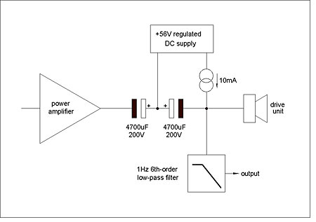
Fig.A Block diagram of the test apparatus.
Isolating the power amplifier from the DC-sensing current is achieved using a decoupling capacitor. But this must be large to achieve a sufficiently low corner frequency in combination with likely speaker voice-coil resistance, and that necessitates the use of an electrolytic type. The problem then is that electrolytic capacitors need to be polarized if they are not to have an uncertain life expectancy, which entails applying a DC polarizing voltage that is larger than the expected peak voltage of the AC waveform from the power amplifier. As I didn't want to risk capacitor failure—apart from anything else, electrolytics of suitable capacity and voltage capability are expensive—I used two 4700µF, 200V electrolytics connected back to back with a regulated polarizing voltage of approximately 56V on their linked positive terminals. (Line regulation is important to prevent low-frequency variations in the mains voltage appearing in the measurements.) Together, these provided a series capacitance of 2350µF (±20%), which even with a 4 ohm load resistance (about that of the CDM1NT's bass-mid driver) assures a high-pass corner frequency of 21Hz or lower.
To remove the AC component from the voltage at the speaker terminals requires a high-slope low-pass filter with an infrasonic corner frequency. I used a sixth-order Butterworth filter with a corner frequency of 1Hz, which provides over 150dB attenuation at 20Hz. This high order of attenuation at audio frequencies reduces the AC (signal) voltage to an insignificant amplitude relative to the DC voltage to be measured. I used a sensing current of 10mA (derived from a constant-current source fed from the polarizing supply), which gives a voltage of 40mV across a 4 ohm resistance while dissipating only 0.4mW within it, so its heating effect is negligible. If we assume a peak–peak music-signal voltage of 50V, the low-pass filter will attenuate this to 0.8µV at 20Hz, which is over 90dB down ref. 40mV. The filter's circuit is shown in fig.B.
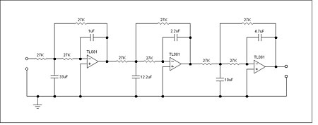
Fig.B Circuit schematic of the 1Hz, sixth-order Butterworth low-pass filter.
For the measurements, the DC voltage across the voice-coil was recorded at intervals of 10 milliseconds with a Pico Technology ADC-212 virtual instrument oscilloscope in data-acquisition mode, using Pico's bundled PicoLog software. The data were then smoothed using a five-second moving average calculation performed in a software utility written for the purpose.—Keith Howard
Footnote 1: C.A. Hendricksen, "Heat Transfer Mechanisms in Loudspeakers: Analysis, Measurement and Design," Preprint 2343, AES 80th Convention, March 1986.
Footnote 2: M. Buck, "Measuring Loudspeaker Voicecoil Temperature," Preprint 4969, AES 106th Convention, May 1999.
|
| |||||||||
- Log in or register to post comments


| Loudspeakers Amplification Digital Sources | Analog Sources Accessories Featured | Music Columns Retired Columns | Show Reports | Features Latest News Community | Resources Subscriptions |
 © 2024 Stereophile
AVTech Media Americas Inc., USA
All rights reserved

