| Columns Retired Columns & Blogs |
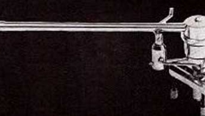
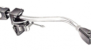
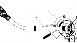
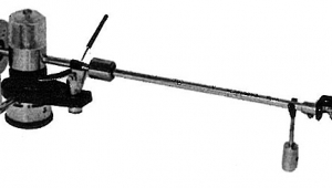
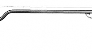
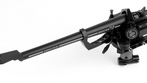
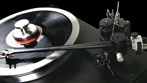
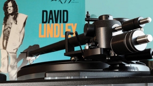
Graham Model 1.5 tonearm Page 2
The dynamic behavior of the arm is critical to overall performance. Real-world records are eccentric and warped. Trying to negotiate such a record subjects the arm to lateral and vertical accelerations. By far the most serious practical problem is that of negotiating a small-radius warp. As the stylus starts to climb the uphill side of the warp, the cantilever is compressed upward, which may significantly increase vertical tracking force. This is bad enough in itself—increased VTF accelerates record wear—but the cantilever may be displaced upward to the extent that the cartridge enters the twilight zone of nonlinearity: either because of suspension overload or operation in the fringe of the magnetic field.
On the downhill side of the warp the cartridge begins to lose contact with the groove. The effective VTF is reduced, which increases distortion, but the ultimate danger is that of complete loss of contact and groove skipping. What's required here is a nimble arm, dynamically able to keep the stylus in the groove while negotiating a roller coaster.
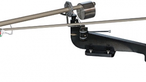
A figure of merit for assessing a tonearm's dynamic performance is the ratio of VTF to effective mass: the greater the better. This (with an important caveat) gives the maximum acceleration in gravitational "g" units that the arm can withstand before leaving the groove. The effective mass for the Graham arm is about 11 grams. Thus, with a VTF of 2.0 grams, the maximum safe acceleration is 2/11, or 0.18g.
What we have ignored so far in the dynamical analysis of the arm are the effects of damping fluid and arm-pivot restoring forces. Damping is normally applied at the pivot of the arm in the form of a fluid. Used in moderation, damping is a good thing. It is not a magic potion that will somehow convert a poor arm into a good one, but it does help an already good arm perform even better by reducing the "Q" of any resonances. Used in excess, damping can backfire by reducing the dynamic capability of the arm. Damping fluid resists acceleration and exacerbates the problems encountered by the arm while negotiating warps.
Another negative complication involves the action of restoring forces acting at the pivot. On some arms the pivot is located above the arm's center of gravity in what is known as a "stable static balance." The analogy suggested by Bob Graham is that of a high-wire artist balancing himself with the use of a large pole which bends at the ends to well below the plane of the wire. The pole confers stability by lowering the center of gravity below the "pivot point," in this case the artist's feet, thus opposing the decentering of the center of gravity. Again, this makes it more difficult for the arm to navigate warps. Once the arm is knocked out of balance by the warp, the arm attempts to steer back to stable balance regardless of what the dynamic situation demands.
I've left geometrical considerations for last because their importance is often exaggerated. I do not believe that a linear-tracking arm is a requirement for the ideal arm. Often, such an arm introduces compromises in the areas of arm rigidity and dynamic behavior that dwarf the theoretical reduction in lateral tracking distortion and the attendant benefit of no side thrust. A 9" effective-length pivoted arm with optimum offset angle and overhang produces a maximum tracking error of 2.33%. For a recorded velocity of 10cm/s RMS, this translates into 0.74% harmonic distortion. In view of the other forms of distortion inherent in phono reproduction, such as tracing and vertical tracking distortions, it's reasonable to accept these levels of lateral tracking distortion at least as subjectively adequate. Essentially all of the lateral tracking distortion is second-harmonic in nature and therefore consonant with the music.
According to Randhawa (Wireless World, March/April 1978), it was not the distortion per se that moved manufacturers to decrease tracking error, but rather the excessive wear resulting from greatly increased side thrust. There was a time when 12" arms were fairly common. The longer pivot-to-stylus distance served to trace a more tangential arc across the grooved surface of the record, but the penalty in terms of increased effective mass far outweighed the benefits.
It is now well established that it was Löfgren in 1938, and not Baerwald in 1941, who provided the first comprehensive mathematical analysis of tonearm geometry aimed at minimizing the lateral tracking distortion weighed by the inverse of the groove radius. This is the key concept: Tracking distortion varies proportionately with tracking error and inversely with groove radius; the quantity to minimize is the tracking error per unit radius. As you get closer to the inner recorded radius, groove modulation increases and the signal/noise ratio decreases. Thus, it makes sense to place the maximum distortion at the outer radii. The standard analysis specifies, for a given effective arm length and inner and outer recorded surface radii, the optimum offset angle and overhang. This solution gives two "null radii" (2.32" and 4.62" from the spindle) at which the cartridge is tangential to the groove. Alignment templates use these null points for setting up the optimum tracking geometry.
Several optional alignments are possible, each of which introduces additional non-geometrical criteria into the analysis. Löfgren himself believed that the annoyance factor of tracking distortion was cumulative with time and proposed an alternative alignment with increased overhang so that the maximum distortion between the null radii would be lower—but at the cost of briefly increasing distortion at the beginning and end of the record. There is no psychoacoustic evidence to support Löfgren's "hypothesis." I find it hard to believe that a small decrease in second-harmonic distortion would reduce the annoyance factor. In fact, quite the opposite is more likely to happen; ie, an increase in even-order harmonic products is more likely to mask more noxious forms of distortion.
NEXT: Page 3 »
|
|
| ||||||||||
- Log in or register to post comments


| Loudspeakers Amplification Digital Sources | Analog Sources Accessories Featured | Music Columns Retired Columns | Show Reports | Features Latest News Community | Resources Subscriptions |
 © 2024 Stereophile
AVTech Media Americas Inc., USA
All rights reserved

