Exposure XV integrated amplifier Measurements

Sidebar 2: Measurements

After running the XV at one-third rated power into 8 ohms for an hour (the recommended measurement preconditioning conditions), the heatsinks grew too hot to touch. I estimated the rear-panel temperature at about 70°C. After listening at even moderate playback levels, the heatsinks reached about the same temperature.

The XV's frequency response, shown in fig.1, reveals the amplifier's band-limited response. The amplifier was down 0.84dB at 20kHz into 8 ohms (top pair of traces, dotted trace is the right channel). When driving 4 ohms, the treble rolloff increased to –1.2dB at 20kHz. Note also that the rolloff begins in the lower treble (down 0.35dB at 10kHz into 4 ohms). While these figures would suggest an audible effect, the XV didn't appear to lack HF extension or "air." The XV's reproduction of a 10kHz squarewave is shown in fig.2. The waveshape is good, but the amplifier's HF rolloff is apparent on the waveform's rounded leading edge.

293Exp15fig1

Fig.1 Exposure XV, line-input frequency response at 2.83V into 8 ohms (top) and 4 ohms (bottom) (0.5dB/vertical div.).

293Exp15fig2

Fig.2 Exposure XV, small-signal 10kHz squarewave into 8 ohms.

Input impedance at the line inputs was 9.1k ohms, slightly less than the specified 10k ohms. At the phono inputs, the input impedance was 490 ohms across most of the band, dipping slightly to 409 ohms at 20kHz. These measurements were made with the MC phono board, which is specified at 470 ohms input impedance. Looking further at the phono stage performance, the RIAA equalization accuracy is moderately good in the left channel, but the right channel has about a 0.5dB negative error in the bass and lower midrange (fig.3). Despite this imbalance, no anomalies were detected during the auditioning. Note also the rapid LF rolloff, typical of European phono stages. Because the XV is an integrated amplifier, the RIAA equalization was measured at the loudspeaker output jacks, and will thus have the power amplifier's frequency response superimposed on it.

293Exp15fig3

Fig.3 Exposure XV, phono-stage RIAA error (right channel dashed, 0.5dB/vertical div.).

MC phono input overload was a very high 25mV at 1kHz (34dB), suggesting that the phono stage will not be overloaded by even the highest-output moving-coil cartridges, and will even accept some moving-magnet levels. The unweighted, wide-band signal/noise ratio of the entire XV, from phono input to loudspeaker output, was a good 65.5dB (left channel) and 63.5dB (right), referenced to 1W output into 8 ohms. The line inputs were considerably quieter, measuring 95dB in both channels from CD input to loudspeaker output, again referenced to 1W output into an 8 ohm load.

Channel separation, measured from the line inputs to the power-amplifier outputs, is shown in fig.4. The left-channel crosstalk (right channel driven, left channel measured) is fairly good, measuring –63dB at 1kHz, decreasing to –42dB at 20kHz. The 6dB/octave rise through most of the trace is indicative of capacitive coupling between channels. The right-channel crosstalk was considerably worse, measuring just –38dB over most of the band, decreasing to –32dB at 20kHz. The flat shape of the right-channel curve might suggest that I was measuring noise, not crosstalk from the driven channel. However, looking at the right-channel signal on an oscilloscope confirmed that the signal was indeed crosstalk. Moreover, there was no difference in line-input S/N between channels that would emulate higher crosstalk in one channel.

293Exp15fig4

Fig.4 Exposure XV, line-input crosstalk, R–L top, L–R bottom )5dB/vertical div.).

Measuring channel separation from the phono inputs to the power-amplifier outputs produced nearly identical curves (fig.5). This suggests that the phono-stage crosstalk is lower than the line-stage and power-amplifier crosstalk, and that the less good right-channel crosstalk occurs in the driver or output stage.

293Exp15fig5

Fig.5 Exposure XV, phono-input crosstalk, R–L top, L–R bottom) 5dB/vertical div.).

Moving to the power-amplifier section, the XV had an output impedance of 0.3 ohms at 20Hz, 0.27 ohms at 1kHz, and 0.47 ohms at 20kHz. These are quite high values for a solid-state amplifier, suggesting that the XV's sound and performance will be dependent on the loudspeaker it is driving. I measured a fairly high level of DC at the loudspeaker terminals: 26.5mV at the right channel and 26.5mV at the left. These figures didn't change with volume-control setting. Volume-control tracking was excellent, with just 0.13dB imbalance between channels at 1W output, increasing slightly to 0.19dB at 10W, and measuring only 0.04dB at 20W output. The XV doesn't invert absolute polarity.

The XV's distortion vs frequency curves at low signal levels are shown in fig.6. The curves were made at 1W into 8 ohms (bottom trace), 2W into 4 ohms (middle trace), and 4W into 2 ohms (top trace). Note the rise in distortion with frequency. Into 2 ohms, the distortion levels are quite high at this low power output, approaching 1% at 10kHz.

293Exp15fig6

Fig.6 Exposure XV, THD+N (%) vs frequency at 2.83V into (from bottom to top: 8 ohms, 4 ohms, 2 ohms.

Although the XV is rated at "40W 8 ohms," I measured a maximum output power (at clipping, defined as 1% THD) of 36.4W (15.6dBW) in both left and right channels into 8 ohms with both channels driven. This figure increased to 37.3W (15.7dBW) when only one channel was driven at a time. Into 4 ohms, the XV's output power actually decreased slightly to 36W in the left channel (12.5dBW), but reached 40.7W (13.1dBW) with one channel driven. (The AC line voltage during these tests was 117V.) These figures are considerably less than the XV's 40Wpc rating. Moreover, the inability to increase its output power suggests that the XV is current-limited, and will behave very differently depending on the load it is asked to drive.

Fig.7 shows the XV's distortion vs power output at 8 ohms and 4 ohms. Note the very sharp knee in the distortion curves; as is the case with amplifiers using regulated power-supply rails, the XV is perfectly well behaved until driven into clipping, when the distortion skyrockets. I didn't measure the XV at significant power output levels into 2 ohms; the designer warned me that driving a 2 ohm load at full power would burn the output transistors' emitter resistors. In addition, the power-output drop measured when driving 4 ohms revealed the XV's current-limited delivery; no more information would be gained by pushing the amplifier beyond its limits. According to designer John Farlowe, however, the XV will drive loudspeakers with 2 ohm impedance dips without difficulty.

293Exp15fig7

Fig.7 Exposure XV, distortion (%) vs 1kHz continuous output power into (from bottom to top at 10W): 8, 4 ohms.

Even when driving such a loudspeaker with music, the stress on the amplifier is considerably less than when driving a 2 ohm dummy load at full output power. Indeed, the Hales System Two Signatures, which saw most of the auditioning time with the XV, have a moderately difficult impedance curve that rarely rises above 6 ohms and dips to 3.5 ohms through much of the bass.

Fig.8 is the XV's harmonic distortion spectrum when driving a 4 ohm load at 2/3 power. The 50Hz test signal appears at the far left, and the harmonic products are seen as spikes at multiples of 50Hz. The second-harmonic product is noticeable at –85dB, there is an almost complete absence of third harmonic, but other odd-order products continue well up into the audioband. Looking at the XV's intermodulation spectrum when reproducing a mix of 19kHz and 20kHz at 2/3 power into 4 ohms (fig.9), we can see a fairly strong 1kHz component, with spikes at multiples of 1kHz. The IM products at 16kHz, 17kHz, 18kHz, and 21kHz are also quite high in level. The same measurement made with the XV driving an 8 ohm load at 2/3 power looked very similar, but the amplitude of the IM products was lower.

293Exp15fig8

Fig.8 Exposure XV, spectrum of 50Hz sinewave, DC–1kHz, at 26W into 4 ohms (linear frequency scale).

293Exp15fig9

Fig.9 Exposure XV, HF intermodulation spectrum, DC–22kHz, 19+20kHz at 24W peak into 4 ohms (linear frequency scale).

Overall, the XV was less impressive on the bench than in the listening room. The fairly high distortion levels, current-limited power output, and low channel separation were far from exemplary. The XV, with its high output impedance, second-harmonic–dominated distortion, and current-limited delivery, behaves more like a tubed amplifier than a solid-state unit. These measurements suggest that careful loudspeaker choice is essential to get the most from the XV. Low-impedance, insensitive, or current-hungry models should be avoided.—Robert Harley

COMPANY INFO
Exposure Electronic
US distributor: Fidelis Music System
460 Amherst Street (Route 101A)
Nashua, NH 03063
(603) 880-4434
ARTICLE CONTENTS

COMMENTS
Ortofan's picture

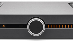
... heat sink for the output transistors, this is it.
Can't believe the designer thought that a simple L-bracket attached to the rear panel was sufficient.

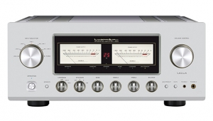
If the author was under the impression that the Exposure's "overall build and parts qualities are excellent" and "the unit is nicely finished", he should have examined a Pioneer Elite A-71, which was a contemporary of the XV and sold for about the same price:
http://www.thevintageknob.org/pioneer-A-71.html

johnnythunder's picture

there was something very special and individual about this Exposure amp and it's contemporaries like the Naim Nait Creek's 4040 and Audiolab's 8000A. In some ways the NAD 3020 is the original of these UK designed integrateds, all quirky and punching way above their weight musically and sonically even if they were not luxury products per se. They all clarified details and penetrated into the music in a very different way than most audio products of their time.

X