| Columns Retired Columns & Blogs |
California Audio Labs Sigma II D/A converter Measurements
Sidebar 3: Measurements
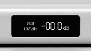
The maximum output level of the California Audio Labs Sigma II was 1.92V, a hair under the CD standard's 2V, and it didn't invert polarity. The source impedance was much lower than specified, at a low 24 ohms across the band, but the processor still wasn't happy driving low impedances. The bottoms of the sinewave clipped at -17dBFS into the admittedly punishing 600-ohm load. I wouldn't recommend using the Sigma with a preamp offering less than a 10k ohm load. In addition, when I played the low-frequency raised-cosine signal that I use to diagnose signal polarity, the unit's output relays chattered—a sign of an over-aggressive DC servo circuit?
Feeding the processor with a CD source at -12dBFS gave the frequency response shown in fig.1 (top traces): flat as expected in the audio band, the top octave rolls off to -0.5dB at 20kHz. The response was almost identical with a pre-emphasized signal (bottom traces, offset by -1dB for clarity), suggesting accurate de-emphasis. Fig.2 shows the Sigma's frequency response when fed with either 48kHz- or 96kHz-sampled data (derived from the Apogee PSX-1000 A/D converter, reviewed by Michael Fremer elsewhere in this issue). The higher sample rate shows the expected doubling of the reproduced signal bandwidth, but what was not expected was the peculiar notch at 22kHz in the 96kHz trace. It is probably benign, however. Channel separation (not shown) was excellent, at better than 90dB below 10kHz, despite both channel outputs sharing the 12AX7A twin-triode output tube.
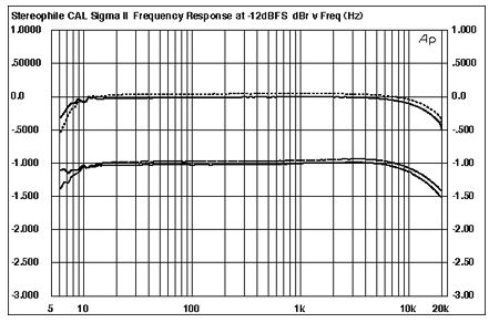
Fig.1 California Audio Labs Sigma II, CD frequency response with (top) and without (bottom) de-emphasis at -12dBFS (right channel dashed, 0.5dB/vertical div.).

Fig.2 California Audio Labs Sigma II, frequency response at -6dBFS at 48kHz and 96kHz sampling frequencies (right channel dashed, 5dB/vertical div.).
Fig.3 shows the spectrum of the Sigma II reproducing a dithered 1kHz tone at -90dBFS with input-data word lengths of 16 bits (top) and 24 bits (bottom). An inconsequentially slight 60Hz AC supply component can be seen in the right-channel traces, this probably due to magnetic coupling from the chunky AC transformer. More important, note that extending the word length to 24 bits gives only about a 6dB lowering of the noise floor, and then only above 2kHz. It may accept 24-bit data, but this processor's dynamic range is limited by noise to about the equivalent of 17 bits. Extending the measurement bandwidth to 200kHz and driving the Sigma with digital black gave the curves shown in fig.4. The ultrasonic peak is due to the noise-shaping used to derive high resolution from a DAC chip with a sigma-delta architecture. Again, the difference between 16- and 24-bit data can be seen to be only about one bit's worth of improvement in dynamic range.

Fig.3 California Audio Labs Sigma II, 1/3-octave spectrum of dithered 1kHz tone at -90dBFS, with noise and spuriae, 16-bit (top) and 24-bit (bottom) data (right channel dashed).

Fig.4 California Audio Labs Sigma II, 1/3-octave spectrum of digital black, with noise and spuriae, 16-bit (top) and 24-bit (bottom) data (right channel dashed).
Nevertheless, the Sigma offered excellent linearity, as shown in fig.5. Any amplitude error in the recovered analog signal is less than 1dB down to -110dBFS or so. The presence of the ultrasonic noise obscured the shape of an undithered 16-bit/1kHz sinewave at -90.31dBFS (fig.6), and this shape was hardly affected by extending the word length to 24 bits (not shown).

Fig.5 California Audio Labs Sigma II, departure from linearity, 16-bit data (right channel dashed, 2dB/vertical div.).

Fig.6 California Audio Labs Sigma II, waveform of undithered 1kHz sinewave at -90.31dBFS, 16-bit data.
Provided the load impedance was kept suitably high, the California Audio Labs DAC was very linear. The highest harmonic on a full-scale 50Hz sinewave output into 100k ohms lay at just -94dB (0.002%). Even at the maximum level into 600 ohms before clipping (fig.7), the second harmonic rose to only a shade over -80dB (0.01%), though now some third harmonic can also be seen. And the processor handled the punishing high-frequency intermodulation test (fig.8) with aplomb, even the 1kHz difference tone remaining below -90dB (0.003%). Again, however, this is with the proviso that the load impedance be kept high.

Fig.7 California Audio Labs Sigma II, spectrum of 50Hz sinewave, DC-1kHz, at -18dBFS into 600 ohms (linear frequency scale).

Fig.8 California Audio Labs Sigma II, HF intermodulation spectrum, DC-22kHz, 19+20kHz at 0dBFS into 100k ohms (linear frequency scale).
The word-clock jitter level, assessed with the Miller Audio Research analyzer and the Julian Dunn analytical signal (11.025kHz with the LSB toggled at 229Hz), was very low: just 181 picoseconds. The spectrum of the jitter in the recovered analog signal is shown in fig.9. The noise floor can be seen to lie around 6dB higher than with the best 16-bit components. The highest-level sidebands are marked with a red "3" (±229Hz, 25.5ps, data-related), and a purple "5" (±377.5Hz, 74.5ps, no idea). There are some other higher-order data-related pairs of sidebands present, but overall this graph demonstrates good jitter rejection.

Fig.9 California Audio Labs Sigma II, high-resolution jitter spectrum of analog output signal (11.025kHz at -6dBFS with LSB toggled at 229Hz). Center frequency of trace, 11.025kHz; frequency range, ±3.5kHz.
Overall, this is good measured performance, let down by only the higher-than-usual noise floor.—John Atkinson
|
| ||||||||||
- Log in or register to post comments


| Loudspeakers Amplification Digital Sources | Analog Sources Accessories Featured | Music Columns Retired Columns | Show Reports | Features Latest News Community | Resources Subscriptions |
 © 2024 Stereophile
AVTech Media Americas Inc., USA
All rights reserved

