| Columns Retired Columns & Blogs |
Bits is Bits? Page 5
Interface Noise: Besides increasing the (low) possibility of amplitude errors, interface noise can also be the cause of timing jitter in a band-limited interface. Consider a link with a time constant of RC, where, at the zero-crossing points, the rate of change of the received interface signal will be equal to Vd/RC (where Vd is the transmitter driving voltage). Thus, peak interface noise of vn results in a jitter noise of peak amplitude given by:
Footnote 10: It is possible that this kind of mechanism is responsible for the reported sound quality differences between different families of logic chips.—John Atkinson
Equation 15:

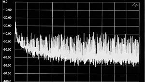
Hence, a peak interface noise 20dB below the driving voltage and a time constant of 100ns will result in 10ns peak jitter due to the noise source. This is of the same order of magnitude of as the jitter due to inter-symbol interference tjRC given by Equation 11 and plotted in fig.13. In practice, jitter due to noise will be wideband, and hence will be largely attenuated by the PLL filter at the receiver. This behavior can be contrasted with jitter due to inter-symbol interference, which will not be heavily attenuated for moderate PLL cutoff frequencies. This argument is given weight by fig.21, which shows the measured jitter spectrum in the experimental receiver for constant audio data (ie, no inter-symbol interference). Here, the jitter is shown to be lower than for the measurements taken with CD-audio tone tracks transmitted over the interface (fig.19), even though the same noise-jitter mechanism is present in both circumstances. However, note that the noise-jitter mechanism can also cause problems with the recovered clock at the receiver output after the PLL, and all clock circuitry between the PLL and converter requires high-speed, low-noise characteristics.
Interface Slew-Rate Imbalance: Another jitter mechanism that can cause problems with biphase-mark coded interface signals is asymmetrical slew rates across the link. If the receiver recovers the embedded interface clock by detecting transitions at every cell edge, as in our original detection model, the difference between the number of positive-going and negative-going detection transitions across a frame will depend upon the number of ones and zeros (and hence the audio word) transmitted. In the limit, the jitter due to slew-rate imbalance will equal the difference between the negative- and positive-going (slew-limited) zero-crossing times. Consider an interface signal with positive- and negative-going slew rates (VSR+ and VSR-, respectively). The peak jitter due to slew-rate imbalance will be:
Equation 16:

Thus, for an interface signal detected using 74HC logic circuitry, where Vd = 2.5V and positive- and negative-going slew rates are 0.5V/ns and 1V/ns respectively, then Equation 16 gives the peak jitter due to slew imbalance as 1.25ns. Moreover, since the ratio of positive- to negative-going cell edges is dependent upon the transmitted audio word value, the jitter is likely to have strong components at audio frequencies (footnote 10).
The problem of slew-rate imbalance interface jitter can be solved by only detecting interface transitions in only one direction. This is the approach adopted in the SAA7274 ADIC used in the experimental receiver circuit, where monitoring the signal on pin 4 using an oscilloscope reveals that only negative-going interface transitions are used to recover the embedded clock.
Jitter error models
To assess the consequences of jitter in a D/A conversion process, we require a DAC jitter-error model. Harris has developed an analytical model for jitter in ADCs, (footnote 11) but the error mechanism in a DA process is different and depends upon the specific DAC architecture employed. In this section we present error models for two classes of DAC (these models are essentially the same as those presented by Hawksford (footnote 12).
First, we consider a Nyquist-sampling DAC with a sample-and-hold unit, in which each of the individual sample values input to the DAC are held until the next sample arrives; we term this a "100% sample DAC." Second, an "impulsive" D/A conversion process is considered, where consecutive output samples do not overlap. This model approximates a pulse-density modulation (PDM) conversion strategy as used by Philips in their oversampled and noise-shaped "Bitstream" converters. The error models' accuracy is established by comparing simulated results against actual measurements on physical DACs where jitter has been purposefully introduced into the interface. This is important: the error models are used to make predictions about the audibility of jitter artifacts. (See "Audibility of Jitter Errors.")
100% Sample DAC: A 100% sample DAC holds the value of a given sample at its output until a new sample arrives. Thus, timing error at the transition between adjacent samples results in a reconstructed analog signal with an "error area" directly proportional to the product of the sample timing jitter and the difference between the sample values (fig.23a). If we denote the normalized sample values as An and corresponding jitter values tjn, then if the jitter amplitude is small compared to the sampling period ts, we can form an error sequence en by scaling the error area by the sampling period:

Fig.23 DAC jitter error models: a) 100% sample DAC (top); b) Impulsive sample DAC (bottom).
Equation 17:

This analysis is similar to Blesser's approach in examining slew limiting in DAC output stages (footnote 13). The frequency-domain representation E100%(f) of this error sequence can be obtained by taking the discrete Fourier transform of en:
Equation 18:

where:
F is the discrete Fourier operator;
N is the number of samples forming the discrete error sequence;
f can take on values of kfs/N where k is an integer;
i is the complex variable √(-1).
Equation 18 indicates that the error spectrum for the 100% model should involve intermodulation components at signal/jitter sum and difference frequencies; this can be confirmed by simulating a jitter error signal using the model.
Fig.24a shows the unjittered spectrum of a 16-bit-quantized, 0dBFS, 10,001Hz audio signal, where the choice of excitation frequency has led to a flat quantization noisefloor even though no dither has been used. Fig.24b shows the same signal, but now corrupted by a 1kHz jitter signal of peak amplitude 10ns. As expected, the error components in the jittered spectrum occur as sidebands at 10kHz ±1kHz at approximately -71dBFS.

Fig.24 Simulated jitter error spectra for 100% DAC model (from top to bottom): a) 10,001Hz at 0dBFS audio, no jitter; b) 10,001Hz at 0dBFS audio, 10ns peak 1kHz jitter; c) 2001Hz at 0dBFS audio, 10ns peak 1kHz jitter.
The An-An-1 factor in Equation 18 makes the magnitude of the error spectrum roughly proportional to the frequency as well as the amplitude of the audio signal. This is illustrated in the simulated error spectrum of fig.24c for a 0dBFS, 2001Hz sinusoid, again jittered at 1kHz; due to the fivefold drop in excitation frequency, the sidebands are now approximately 14dB lower than the 10kHz example. Additional simulations not shown here have revealed that the error spectrum for a 100% DAC is almost identical to that obtained from the ADC jitter model developed by Harris (footnote 14).
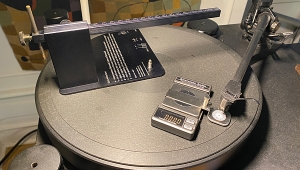
The accuracy of the error model can be verified by performing measurements with physical DACs where a known jitter signal is introduced into the digital interface signal; this technique has also been used by Peter van Willenswaard (footnote 15). Fig.25 shows the test arrangement used. A CD transport's digital output is connected to a custom digital interface unit, which comprises a transmitter and a receiver circuit very similar to that shown in fig.4. The receiver locks on to the incoming digital interface signal and passes the unscrambled data to the transmitter, which performs a complementary function and outputs an interface signal to the DAC under examination. Now the edge timing on the output of the transmitter is controlled by the recovered clock in the receiver, so applying signals to the control voltage on the receiver PLL allows direct injection of jitter into the digital interface signal.

Fig.25 Test setup for measuring DAC sensitivity to interface jitter.
Footnote 10: It is possible that this kind of mechanism is responsible for the reported sound quality differences between different families of logic chips.—John Atkinson
Footnote 11: S. Harris, "The Effects of Sampling Clock Jitter on Nyquist Sampling Analog-to-Digital Converters, and on Oversampling Delta-Sigma ADCs," JAES, July/August 1990, Vol.38, pp.537-542.
Footnote 12: M.O. Hawksford, "Digital-to-Analog Converter with Low Inter-Sample Transition Distortion and Low Sensitivity to Sample Jitter and Transresistance Amplifier Slew Rate," presented at the 93rd AES Convention, San Francisco, October 1992.
Footnote 13: B.A. Blesser, "Digitization of Audio," JAES, October 1978, Vol.26.
Footnote 14: Harris, ibid.
Footnote 15: Peter van Willenswaard, Stereophile, October 1991, Vol.14 No.10, pp.63-69.
NEXT: Page 6 »
|
| |||||||||
- Log in or register to post comments


| Loudspeakers Amplification Digital Sources | Analog Sources Accessories Featured | Music Columns Retired Columns | Show Reports | Features Latest News Community | Resources Subscriptions |
 © 2024 Stereophile
AVTech Media Americas Inc., USA
All rights reserved

