| Columns Retired Columns & Blogs |
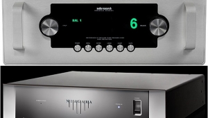
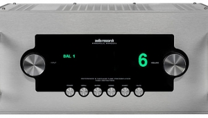
Audio Research Reference 1 preamplifier & VT200 power amplifier Measurements, Audio Research VT200
Sidebar 4: Measurements, Audio Research VT200
A full set of measurements of the Audio Research VT200 was made using its balanced inputs, with selected measurements repeated in the unbalanced mode where noted below. Also, except as indicated, all balanced measurements were taken from the output tap corresponding to the load impedance, and unbalanced readings from the tap with the value closest to the load impedance. The center-tap connection was used only where noted.
Following its 1/3-power, one-hour preconditioning test, the VT200 ran typically hot for a tube power amplifier—but not surprisingly so, considering its power rating.
The input impedance measured 233k ohms, balanced, 100k ohms unbalanced (96k ohms unbalanced connected to the output center-tap connection). The output impedance measured 0.89 ohms at 1kHz and 0.96 ohms at 20kHz (8 ohm load, 8 ohm balanced output tap). The voltage gain measured 22.2dB into 8 ohms (26.4dB unbalanced, 21.4dB unbalanced with a center-tap connection). The signal/noise ratio at 1W into 8 ohms measured 88.7dB over a 22Hz-22kHz bandwidth unweighted, 85.7dB over a 10Hz–500kHz bandwidth unweighted, and 97dB A-weighted.
The VT200 is noninverting when driven from its positive, unbalanced input; at the balanced, XLR input terminal, pin 2 is positive. DC offset measured a very low 1.5mV in the left channel, a still low 12.2mV in the right.
Fig.6 shows the VT200's frequency response; the 4 ohm balanced and unbalanced results, not shown, differed from the 8 ohm balanced reading by less than 0.1dB. The result for a simulated real load is typical of the deviation seen with all amplifiers having high output impedances. In this case, the deviations are relatively mild: At about 1 ohm (8 ohm balanced tap), the VT200's output impedance is lower than average for a tube amplifier. The 10kHz squarewave response (fig.7) is excellent for a tube amplifier, with only a very small ripple visible at the leading-edge corners. The 1kHz squarewave (not shown) is close to textbook-perfect.

Fig.6 Audio Research VT200, frequency response at (from top to bottom): 1W into 8 ohms; 2.828V into simulated loudspeaker load (0.5dB/vertical div., right channel dashed.)
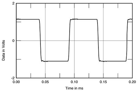
Fig.7 Audio Research VT200, small-signal 10kHz squarewave into 8 ohms.
Fig.8 shows the VT200's crosstalk. The difference in separation between the two channels should be of no audible consequence at these low levels.

Fig.8 Audio Research VT200, crosstalk (from top to bottom): L-R, R-L (10dB/vertical div.).
The THD+noise vs frequency curves are plotted in figs.9 and 10, the distortion waveform at 5W into 4 ohms in fig.11. The latter is heavily third-harmonic, though additional components are present also. The waveforms into 2 and 8 ohms (not shown) were similar.

Fig.9 Audio Research VT200, balanced, THD+noise vs frequency at (from top to bottom at 1kHz): 4W into 2 ohms, 2.828V into simulated loudspeaker load, 2W into 4 ohms, and 1W into 8 ohms (right channel dashed).

Fig.10 Audio Research VT200, unbalanced, THD+noise vs frequency at (from top to bottom at 1kHz): 4W into 2 ohms, 2W into 4 ohms, and 1W into 8 ohms (right channel dashed).
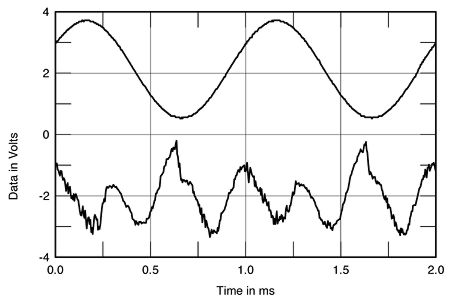
Fig.11 Audio Research VT200, 1kHz waveform at 5W into 4 ohms (top), distortion and noise waveform with fundamental notched out (bottom, not to scale).
The VT200's output spectrum driving 50Hz at 99W into 4 ohms is shown in fig.12. The distortion products are low, but not remarkably so: -52dB (0.25%) at 100Hz and -64dB (approximately 0.06%) at 150Hz. Note that the second harmonic is now the highest in level. Looking at the spectrum of the VT200's output while it drives a combined 19+20kHz signal at 73W into 4 ohms (not shown), the intermodulation product at 1kHz was at -79dB (about 0.012%) while the 18kHz product was at -58dB (about 0.12%). (Visible clipping was present above this output with this demanding input signal.) At 71W into an 8 ohm load, the IM was lower: about 0.006% at 1kHz, 0.08% at 18kHz.
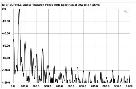
Fig.12 Audio Research VT200, output spectrum, DC–1kHz, 50Hz at 99W into 4 ohms (linear frequency scale).
The continuous 1kHz THD+noise vs output power curves for the VT200 are shown in figs.13 and 14. The discrete clipping levels for the VT200 are shown in Table 1. The maximum power measures less than the specified 200Wpc, though this figure is reached at 10% THD+noise. The low line voltage certainly accounted for some of this discrepancy, but not all. Note that the line voltage with the amplifier off measured about 4V higher than the specified values in Table 1; the amplifier draws enough current to cause the additional line-voltage sag. Also, as no safe, convenient provision is made for the user to adjust the bias—it requires a voltmeter and opening the amplifier—I measured the VT200 as delivered by WP: ie, with the same characteristics with which he auditioned it. Tweaking the bias might well further increase the power output.

Fig.13 Audio Research VT200, balanced 4 ohm tap, distortion (%) vs continuous output power (W) into (from bottom to top at 20W): 4 ohms, 8 ohms, and 2 ohms (one channel driven).
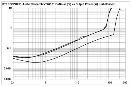
Fig.14 Audio Research VT200, unbalanced 4 ohm tap, distortion (%) vs continuous output power (W) into (from bottom to top): 8 ohms, 4 ohms, and 2 ohms (one channel driven).
Table 1 Audio Research VT200: Discrete Clipping levels
| (1% THD+noise at 1kHz) | |||
| Both Channels Driven | One Channel Driven | ||
| Impedance | W (dBW) | W (dBW) | |
| ohms | L | R | L |
| 8 | 141 (21.5) | 142.4 (21.5) | 147 (21.7) |
| 105V | 105V | 106V | |
| 4 | 139.6 (18.4) | 139.5 (18.4) | 147.5 (18.7) |
| 105V | 105V | 106V | |
| 2 | 132 (15.2) | ||
| 106V | |||
John Atkinson also measured the VT200's output power, but this time using the Miller Audio Research Amplifier Profiler to generate a low-duty-cycle 1kHz toneburst (10 cycles on, 40 cycles off) to more closely simulate music drive. The results from the amplifier's unbalanced 4 ohm tap (one channel only driven) are shown in fig.15. Into 8 ohms (black trace), 104W was available at a 1% THD+N limit, with 163W available into 4 ohms (red trace). Relaxing the THD limit to 3% gave 174.7W into 4 ohms. Less power was available into loads lower than the transformer tap: 159W into 2 ohms (blue trace) and 28W into 1 ohm (green trace). The maximum current available from this transformer tap was just under 9A, suggesting that the tap is actually optimized for a load slightly lower than 4 ohms.
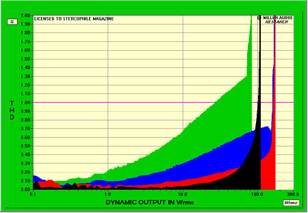
Fig.15 Audio Research VT200, unbalanced 4 ohm tap, distortion (dB) vs dynamic output power into 8 ohms (black), 4 ohms (red), 2 ohms (blue), and 1 ohm (green) (one channel driven).
The use of multiple output transformer taps enable the user to tradeoff maximum output voltage against output current, in order to best match the loudspeaker load. With very low impedance loads, the 2 or 1 ohm transformer taps will be optimal. Fig.16 shows the power vs distortion curves for the 1ohm unbalanced output. While the clipping power into 8 ohms is reduced compared with 4 ohm tap—28.6W vs 104W—this tap can source much greater current, making it perform much more like a voltage source. The 1% THD-limited powers were now 55.7W into 4 ohms, 100.5W into 2 ohms, and 156W into 1 ohm (162.3W into 1 ohm for a 3% THD limit). The maximum output current from this tap was a very healthy 12.5A.

Fig.16 Audio Research VT200, unbalanced 1 ohm tap, distortion (dB) vs dynamic output power into 8 ohms (black), 4 ohms (red), 2 ohms (blue), and 1 ohm (green) (one channel driven).
All these tests were performed using a toneburst signal which means that the amplifier doesn't load down the AC line. It appears, therefore, as though the VT200 really isn't a 200Wpc amplifier. But the shortfall is negligible. Other than this, the Audio Research Reference 1 and VT200 produced a solid set of measurements, certainly about as good as they get for tube designs.—Thomas J. Norton
|
| ||||||||||
- Log in or register to post comments


| Loudspeakers Amplification Digital Sources | Analog Sources Accessories Featured | Music Columns Retired Columns | Show Reports | Features Latest News Community | Resources Subscriptions |
 © 2024 Stereophile
AVTech Media Americas Inc., USA
All rights reserved

