| Columns Retired Columns & Blogs |

I remember that experience well. My wife still says that they were the best she has ever heard.
The Artemis Eos Signature's plot of impedance magnitude and phase vs frequency is shown in fig.1. (Logistical difficulties with the enormous Base Module meant that I couldn't measure its impedance.) The speaker is basically easy to drive, remaining above 6 ohms over almost all the audio band. The tuning of the reflex port is indicated by the "saddle" in the magnitude trace centered on 42Hz, which implies reasonable low-frequency extension even without the bass module. Note the slight wrinkles in the traces at 230Hz and 400Hz; these suggest that there are cabinet resonances present at these frequencies (though given the rocklike construction of the cabinet, this is hard to believe).
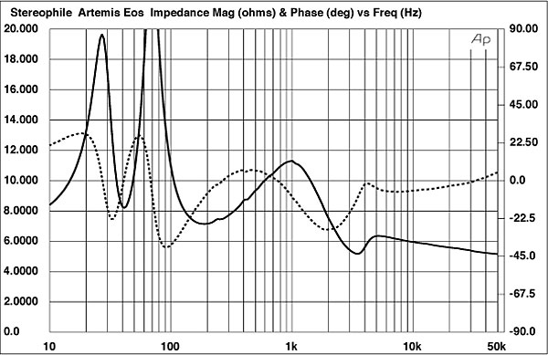
When it came to measuring the Eos' sensitivity, I had some problems in that the B-weighted figure I obtained, 84dB/2.83V/m, was significantly lower than specified. I was also bothered by a rather hollow quality to the speaker's sound, which I usually associate with a treble suckout of some kind. Curiously, when I inverted the electrical connection to the tweeter, the measured sensitivity increased to a more reasonable 87dB and the hollow character disappeared. More on this later.
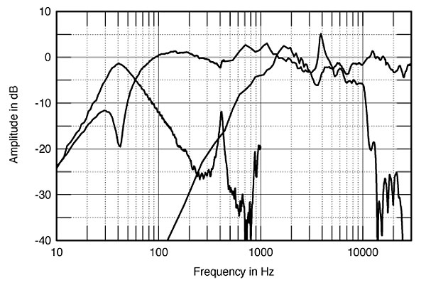
The Signature's external crossover made it possible to examine the intrinsic behavior of the drive-units. Fig.2 shows the unequalized responses of the tweeter, woofer, and port. The latter is the bandpass response centered on the woofer's minimum-motion point at 42Hz. Note that it has a vicious-looking resonant spike at 400Hz, the frequency of one of the wrinkles in the impedance plot. The reflex port acts like an organ pipe at this frequency; fortunately, the fact that the port faces the speaker's rear will reduce any subjective problems due to this resonance (though there is a slight glitch in the woofer's response at the same frequency). The woofer handles the range above 70Hz. But without any crossover in circuit, it suffers from a fierce resonance, probably due to a cone breakup mode at 4kHz.
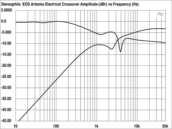
But the Eos Signature is meant to be used with its crossover, whose electrical response is shown in fig.3. The slopes are very gentle, but more important, note that Artemis' designer has applied both a notch at 4kHz to the woofer feed to reduce the effect of the cone mode, and a degree of downward tilt through the midrange to compensate for the drive-unit's inherently rising response. The tweeter also has a slight suckout in its drive, to compensate for a peak between 1.5kHz and 2.5kHz in its raw on-axis output.
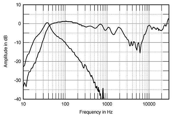
The equalized responses of the individual drivers are shown in fig.4. Both tweeter and woofer are now flat within their passbands. However, there is an area of broad overlap: between 2kHz and 8kHz, both drivers contribute to the overall response. This has ramifications that will emerge in a moment.

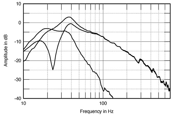
Digressing slightly, fig.5 shows the Eos Base Unit's performance. The port is tuned to a very low 23Hz, with its useful output extending an octave higher in frequency. The woofer takes over above 40Hz, with then a slow rollout above 70Hz. The top trace in fig.5 is the complex sum of the woofer and port responses, taking the physical distance between the two radiating surfaces into account. The Base Module basically covers the 25–55Hz bandpass, which should usefully complement the low-frequency output of the Eos Signature satellite.
That it does so is confirmed by fig.6. The Base Module's response is repeated on the left side of fig.6, with the complex sum of the Eos' woofer and port to its right. But as KR stated, there is no high-pass filter in the Eos Signature's feed, meaning that it has to handle a full-range signal even when coupled with the Base Module. The result is a possible compromise in ultimate dynamic range.
On the right of fig.6 is the farfield response of the Eos on the tweeter axis with the tweeter connected in the correct polarity. Note that the graph is dominated by a large suckout covering the region where the tweeter and woofer overlap. (Both speakers were identical in this respect.) By contrast, fig.7 shows the response with the tweeter connected with inverted electrical polarity: it is now impressively flat throughout the treble. Yet KR much preferred the sound with the tweeter connected so as to give a measured crossover suckout—an enigma until you consider that Artemis recommends that the Eos be auditioned from at least 8' away, and preferably more. At listening distances less than this, the listener's perception of the sound will be dominated by the on-axis response, with its suckout. Certainly when I auditioned the speaker during my measuring, I was only about 4' away. But at farther distances, the speaker's power response increasingly affects the perceived balance, and the power response will not be affected by on-axis interference effects.
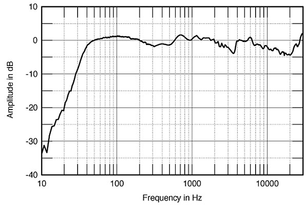
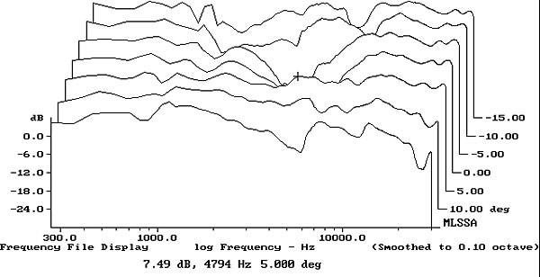
Fig.8 shows the lateral dispersion of the Eos Signature, normalized to the tweeter-axis response (which means that just the changes are shown). The treble "horns" indicate that the sound to the speaker's sides does not suffer nearly so much from the crossover suckout. The reverberant field in the room will therefore be much more evenly balanced. In addition, the plot of the Eos Signature's vertical dispersion (fig.9) suggests that for me to measure the Eos on what intuitively appeared to be the reference axis—level with the tweeter, some 41" from the floor when the speaker sits on the Base Module—was misguided. The speaker's balance becomes significantly flatter through the treble for listeners who sit with their ears around 30" from the floor.
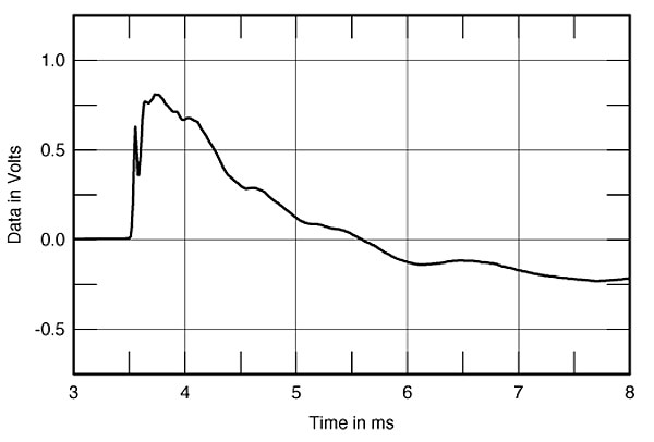
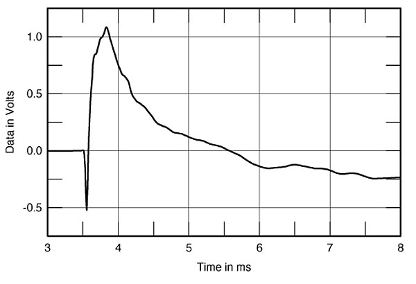
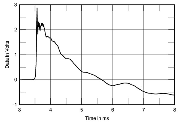
The lack of drive-unit integration on the tweeter axis can also be seen in the time domain. Fig.10, for example, shows the Eos' step response with the tweeter connected in the correct polarity. The HF unit's output is the small up/down spike of energy just after the 3.5ms mark, followed by the woofer. Both units are connected in the same positive acoustic polarity, but the performance is not time-coherent on this axis. Fig.11 shows what happens when the tweeters' electrical polarity is inverted. You can now see that the tweeter is connected with the opposite acoustic polarity to the woofer. However, the return of its step to the time axis now coincides with the rise in the opposite direction of the woofer step, implying flat frequency response on this axis with this connection, as was shown by fig.7. And fig.12 shows the step response on a low axis: now it can be seen that both tweeter and woofer step responses coincide in time, giving both time-coherent performance and a flat response. (Ignore the different scaling and the extra HF overshoot on this graph, which are due to a different anti-aliasing filter being used and a different level adopted for the measurement.)
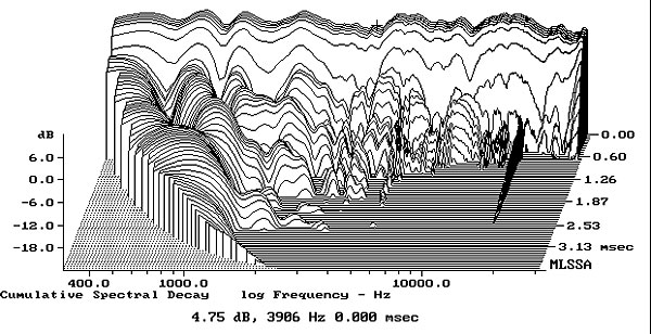
The Eos Signature's cumulative spectral-decay plot on this optimal axis is shown in fig.13. Some low-level hash can be seen in the mid-treble, with a resonance apparent just below 4kHz; this is presumably due to the woofer mode seen in fig.2. This behavior probably explains why KR was bothered by a roughness in the midrange at very high levels.
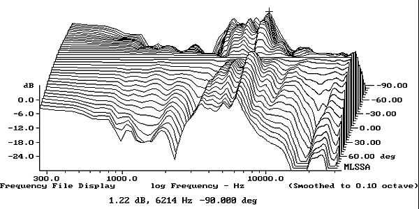
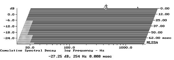
Finally, while the cabinet was dead to the knuckle-rap test, there was a glitch in the impedance trace at 250Hz. Fig.14 shows a waterfall plot calculated from the output of a plastic-tape accelerometer fastened to the Eos' sidewall. Yes, there is a mode present at this frequency, but it is so far down in level that it is safe to say that it will be subjectively innocuous. (See the B&W and NHT reviews elsewhere in this issue for more typical vibration behavior, plotted to the same scale.)
Assuming the review samples were wired correctly, the crossover, baffle slope, and drive-unit polarity seem optimized for listeners sitting either close and low or far away. Assuming that those conditions are met, the Artemis Eos Signature's measurements are respectable indeed.—John Atkinson
|
| ||||||||||


| Loudspeakers Amplification Digital Sources | Analog Sources Accessories Featured | Music Columns Retired Columns | Show Reports | Features Latest News Community | Resources Subscriptions |
 © 2024 Stereophile