| Columns Retired Columns & Blogs |
Arcam DiVA A85 integrated amplifier Measurements
Sidebar 3: Measurements
Having measured a number of idiosyncratic tube amplifiers in the last few issues, I was pleased to get a straightforward solid-state design on the test bench. With its volume control set to its maximum, the Arcam DiVA A85's voltage gain into 8 ohms was a sensible 32.5dB. (So many integrated amplifiers offer far too much gain for any practical combination of source and loudspeaker.) At this volume-control setting, the A85 clips with a 600mV input level, which is well within the reach of any modern source component I can think of. Its input impedance at 1kHz was a moderate 19k ohms, and the amplifier didn't invert signal polarity.
The output impedance was a fairly low 0.21 ohm over most of the audioband, rising inconsequentially at 20kHz to 0.25 ohm. While this implies an 8 ohm damping factor of 32-40, this is sufficiently high to ensure that any modification of the A85's frequency response due to its interaction with the manner in which the loudspeaker's load impedance changes with frequency will be small (fig.1, top trace). This graph also shows a very slight response rise below 20Hz—DC servo action?—and a sensible ultrasonic rolloff that cuts in a little earlier with lower-impedance loads. This rolloff can be seen to slightly slow the rise of a 10kHz squarewave (fig.2), but there are no signs of instability. The 1kHz squarewave shape (not shown) was perfect.
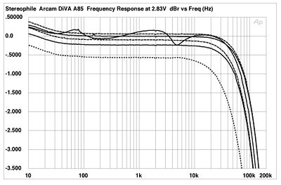
Fig.1 Arcam DiVA A85, frequency response at (from top to bottom at 2kHz): 2.83V into dummy loudspeaker load, 1W into 8 ohms, 2W into 4 ohms, 4W into 2 ohms (right channel dashed, 0.5dB/vertical div.).
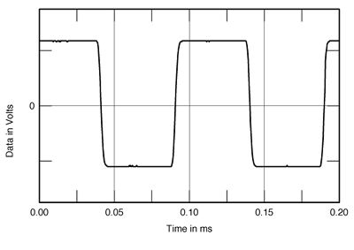
Fig.2 Arcam DiVA A85, small-signal 10kHz squarewave into 8 ohms.
Fig.3 shows the action of the A85's tone controls set to their maximum and minimum positions, while the central pair of traces shows the response with the Tone Defeat button pushed. The bass and treble controls each provide 12-15dB of boost or cut, which is a little on the high side for my tastes. Crosstalk between the channels (not shown) was beneath the noise floor below 1kHz, rising to -50dB (L-R) and -63dB (R-L) at 20kHz, due to the usual capacitive coupling. While the top-octave channel separation is lower than I like to see, it should have no subjective consequences.
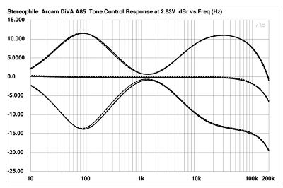
Fig.3 Arcam DiVA A85, effect of tone controls set to their maximum and minimum positions (right channel dashed, 5dB/vertical div.).
The level of distortion and noise remained below 0.015% across most of the audioband into both 8 and 4 ohm loads, rising slightly to around 0.025% at 40kHz (not shown). However, into 2 ohms with continuous drive, it rose to around 0.045%, which, while still low, suggests that the A85 has to work harder than it really likes into this demanding load. The waveform of the distortion (fig.4) is predominantly third-harmonic, which bodes well for sound quality. This can also be seen in fig.5, the spectrum of the amplifier's output while it drove a high-level low-frequency tone into 4 ohms. Even close to clipping into this load, the third harmonic lies at -70dB (0.03%), and all other harmonics are at -90dB or below.
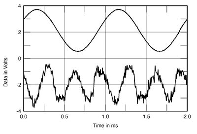
Fig.4 Arcam DiVA A85, 1kHz waveform at 35W into 4 ohms (top), distortion and noise waveform with fundamental notched out (bottom, not to scale).
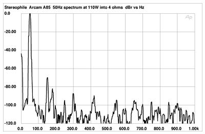
Fig.5 Arcam DiVA A85, spectrum of 50Hz sinewave, DC-1kHz, at 110W into 4 ohms (linear frequency scale).
NEXT: Measurements part 2 »
|
|
| ||||||||||
- Log in or register to post comments


| Loudspeakers Amplification Digital Sources | Analog Sources Accessories Featured | Music Columns Retired Columns | Show Reports | Features Latest News Community | Resources Subscriptions |
 © 2024 Stereophile
AVTech Media Americas Inc., USA
All rights reserved

