Arc Angles: Optimizing Tonearm Geometry Page 3

Another factor that graphs like fig.3 should state is whether RIAA weighting is applied, as suggested by J.K. Stevenson. Because the RIAA deemphasis (ie, replay) curve, ignoring the IEC amendment (footnote 12), declines from +19.4dB at 20Hz to –19.5dB at 20kHz (using the equation in IEC 60098)—an average rolloff of 13.0dB/decade or 3.9dB/octave—Stevenson suggested modifying Baerwald's distortion equation to account for this. If this change is made, then the 1.07% maximum second-harmonic distortion of the red trace of fig.3 is reduced to 0.68%.

The justification for this is perfectly reasonable, of course, but I still wish Stevenson had never suggested it, for three reasons:

1) it introduces confusion between distortion figures and graphs that have or haven't been RIAA-weighted;
2) there are parts of the RIAA curve where the effective slope is less than 3.9dB/octave, notably between 500Hz and 2kHz, where the average slope is 2.6dB/octave and the second harmonics fall at frequencies where the ear has high sensitivity; and
3) intermodulation distortion introduces sum and difference components: the former are reduced in relative level by the RIAA EQ, but the latter are increased.

It isn't clear from the figures alone whether LTED will be audible, particularly as the dominant second-order nonlinearity is known to be quite benign. Settling the issue by listening test is the only way to be sure, and the only way this can be reliably achieved, without other unknowns intruding, is by digitally simulating LTED. I did this back in 2004, when writing a feature for Hi-Fi News (footnote 13) that asked whether radial-tracking arms are justifiable, and the Windows software utility I wrote to perform the simulation remains available from my website's freeware page, if you'd like to determine the issue for yourself (footnote 14). I concluded that the worst-case LTE distortion of an optimally aligned arm of 9" effective length is audible—a finding that, assuming you don't try the software yourself, may reassure you that the rest of this article isn't built on sand.

A couple of further observations about LTE distortion before we move on:

First, LTE distortion affects only the stereo groove's lateral modulation, not its vertical modulation, so it will be heard most obviously toward the center of the stereo soundstage. Vertical modulation is affected by its own tracking-error distortion mechanism caused by disparities between record slant angle and cartridge vertical tracking angle—a tale beyond the remit of this article, and even more complex (and perhaps subjectively more significant) than the one unfolding here.

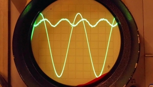
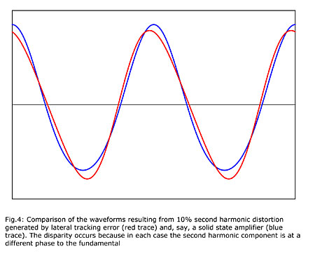
Second, the nature of the distortion introduced by LTE is worth noting. Fig.4 compares the waveform resulting from 10% second-harmonic distortion introduced by lateral tracking error (red trace) to that resulting from the same amount of second-harmonic distortion in, say, a solid-state amplifier (blue trace), the high level of the distortion being to make the disparity in the waveforms clear. The difference arises because the cosine phase of the second harmonic in the LTE case is 90° to the fundamental. To the best of my knowledge, no one has ever demonstrated whether this difference in harmonic phase can be heard or is subjectively irrelevant, even though it can occur elsewhere in audio equipment. I highlight it merely as an engaging curiosity.

Disc Dimensions
The next matter that needs addressing is which maximum and minimum radii to assume for the modulated portion of the record groove, since disagreement on this—more often implicit than explicit—is rampant. Here I restrict the discussion to LP, since I can't imagine that there are many people reading this who would like to optimize their arm/cartridge alignment for 7" singles.

Let's first dispose of the maximum allowable radius of the modulated portion of the groove, since this is stated in IEC 60098 (footnote 15, clause 8.5) as 146.3mm, equivalent to 5.76". This includes a minimum of one turn of "plain" (unmodulated) groove, but that's nothing to fret about because the inner radius is actually the more important figure. As you can see from fig.3, the distortion due to LTE rises rapidly in this region, so if we overestimate the minimum radius, end-of-side distortion will sometimes be worse than anticipated. And guess what? This overestimation of the minimum radius is precisely what many writers on this topic have done.

There is a widespread misconception that the minimum allowable radius for the modulated portion of an LP groove is 60.325mm. Well, it isn't. When I laboriously measured my LP collection 30 years ago, I found a significant proportion had minimum radii down to 58mm, which I subsequently recommended as a realistic figure to use in alignment calculations. IEC 60098 doesn't explicitly state a minimum modulated radius, but it can be calculated from the specified locked groove diameter (106.4mm, ?0.8mm), and minimum number of turns (1) and acceptable pitch (6.4mm, ?3.2mm) for the runout groove. If you do the arithmetic (53.2–0.4+3.2), it turns out that the minimum permissible radius for the modulated portion of the groove is 56mm.


Footnote 12: See K. Howard, "Cut and Thrust," Stereophile, March 2009, Vol.32 No.3.

Footnote 13: K. Howard, "Straight Line to Nowhere?," Hi-Fi News, December 2004.

Footnote 14: www.audiosignal.co.uk/freeware.html.

Footnote 15: IEC 60098, third edition, 1987-11: "Analogue Audio Disk Records and Reproducing Equipment," available from www.iec.org.

ARTICLE CONTENTS

COMMENTS
scho2684's picture

Hi there,
Thanks for this very interesting explanation.

There are 2 things though:
It is stated that it would be good to have a alignment tool delivered with cartridges that obviously is referring to the cartridge body:

I have found that cantilevers and styluses are never 100% aligned correctly, so how to deal with this?

The other thing is the Lofgren B method on which you comment that the approach does not make sense to you because of, as I read it, the higher distortion at the end of the disc.

If I look at my records, most of them don't have modulated grooves there where Lofgren B is exceeding the distortion of the max mid area distortion of the Bearwald, so therefore I think that Lofgren B is the better one...(for me at least)
X