| Columns Retired Columns & Blogs |
Linn LK1 preamplifier & LK280 power amplifier
This review should have appeared more than a few months ago. When I reviewed Linn's Troika cartridge back in the Fall of 1987, in Vol.10 No.6, Audiophile Systems also supplied me with a sample of the Linn LK1 preamplifier and the LK2 power amplifier, which I had intended to review in the due course of things. As it transpired, however, I was less than impressed with the LK2, finding, as did Alvin Gold back in Vol.9 No.2, that while it had a somewhat laid-back balance, it also suffered a pervasive "gray" coloration, which dried out recorded ambience and obscured fine detail.

I suspect that Linn themselves also had had reservations over the LK2's sound; a revised version, renamed the LK280, was introduced a year ago at the 1988 SCES. When I learned that the '280 was to be launched, I naturally put the review on hold until I could get my hands on a sample of the new amplifier. As things transpired, this was not until December last year and I then got deeply involved in a number of other projects, most notably my quest to find good, affordable loudspeakers, which developed into a full-scale education into what makes speakers tick. It wasn't until late April of this year, therefore, that I was able to devote serious time and energy to this review.
This apology over, Linn Products is probably better known for their turntables, tonearms, and cartridges than for their loudspeakers and electronic components. They take all their products very seriously, however, and have put together a fine collection of some of the more inventive engineers in the UK. (It doesn't hurt Linn being based in Glasgow, Scotland, amid the UK branches of some of the more high-tech companies around, such as Hewlett-Packard.) Their preamplifier and power amplifier were launched in late 1985 and have become, I understand, steady sellers.
The LK1
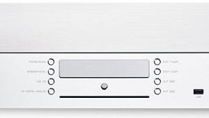
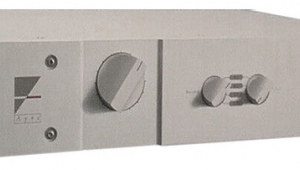
Linn's LK1 is an unusual-looking preamplifier, its over-square, squat black chassis devoid of conventional knobs and switches. Instead, a recessed square section on the left-hand side of the molded front panel contains a keypad of rubber pushbuttons to select source, balance left/right/ volume up/down, mute, Record, and Memory.
Above the buttons, a green LED indicates power-on, with other green LEDs indicating the source selected, red LEDs indicating a source selected to be sent to one of two tape recorders, and a final red LED that flashes when the LK1 has received and understood a command from the infra-red remote control. (This duplicates the front-panel controls, though it also carries a number of additional buttons, presumably to cater to future, unspecified Linn products.) A microprocessor and associated circuitry carried on a vertical printed circuit board behind the front panel control all the input switching and offer considerable sophistication. A different source from that being listened to can be selected for recording; combinations of pushbuttons, using the first as a Shift key, can switch the balance control to full left or right and center it again; the "Mem" key can be used to store and recall current volume and balance settings for any source; and the controls, once set, can also be locked out to avoid them being inadvertently disturbed (at a party, for example). About the only operational idiosyncrasy—and that trivial—is that you cannot record from the MM input when listening to MC and vice versa. An on-board battery preserves memorized settings for several months.
The front-panel and remote controls set and reset DC voltages that control solid-state CMOS switches, these located on the main double-sided pcb that occupies most of the interior space. The advantages of such nonmechanical switching are twofold: first, there is nothing to wear out; second, the switches can be placed at the optimum point in the signal path, avoiding both the use of unnecessarily long or convoluted pcb tracks and of hardwiring looms that are time-consuming to put together in manufacture. Aluminum chassis apart, the LK1, for example, consists of just four assemblies: the switching pcb, connected by ribbon cable to the main audio pcb, which also carries the power supply and voltage-regulator circuitry as well as all the input and output sockets apart from the two pairs of gold-plated phono sockets for the MM and MC inputs, a small rear-panel pcb carrying the disc-input jacks, and a power transformer shielded in a steel can. The result is an electronic component that can be manufactured efficiently and easily tested automatically.
Following the circuit from the MC input sockets, the signal is carried by short twisted-pair connections to the board. Unusually, the input is AC-coupled via what appears to be a tantalum-electrolytic capacitor (though it could be a solid-aluminum type). A cascoded differential amp, using bipolar transistors, provides the first stage of amplification, with a servo circuit based on half of an LM358 dual op-amp chip (this a low-power type with high DC gain) rejecting DC. The signal from the MM input jacks is also carried via a twisted-pair connection to the main board, where it, too, is AC-coupled, this time via what appears to be a small-value polycarbonate cap. The input shunt capacitance is set by a polystyrene cap and the first half of the MM circuit seems similar to the MC, with lower gain, of course. Both MM and MC amplifier stages feed a DG309 analog switching chip, with then a further common stage providing, I believe, the final, low-frequency section of the RIAA equalization. Wire links in this section need to be snipped if a MC cartridge with a nominal output greater than 500µV/cm/s is to be used, and the equalized and amplified output signal is AC-coupled to the input switching chips, these another pair of DC-controlled DG309s.
Four pairs of line-level signals—Tuner, Aux, and two Tape recorders—enter via Linn-manufactured, pcb-mounted XLR sockets and are also taken to the input switching chips. The selected source signal then passes to the active volume control, this offering 256 discrete steps—enough that the action of the control sounds to be continuous—implemented by more DG309 ICs and an Analog Devices AD7528 DAC, here used as a switched resistor ladder. (Feed a digital word into a DAC's input data terminals, drive the chip's voltage reference pin with the analog signal, and the output should be a signal current proportional to the value of that word.)
The final output stage feeds two sets of outputs in parallel. As noted, with the exception of the disc inputs, all the in/out socketry consists of XLRs, two 5-pin male types carrying stereo in/out signals for the two tape loops, and 3-pin males provided for the two additional line-level inputs and the two pairs of outputs. These are thus nonstandard in two ways: in usual professional practice, a male XLR socket denotes an output rather than an input; and Linn wires its sockets to carry a pair of unbalanced signals rather than a single balanced signal, with pin 1 the ground, pin 2 the left channel, and pin 3 the right.
|
| ||||||||||
- Log in or register to post comments


| Loudspeakers Amplification Digital Sources | Analog Sources Accessories Featured | Music Columns Retired Columns | Show Reports | Features Latest News Community | Resources Subscriptions |
 © 2024 Stereophile
AVTech Media Americas Inc., USA
All rights reserved

