| Columns Retired Columns & Blogs |
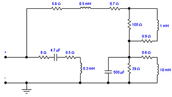
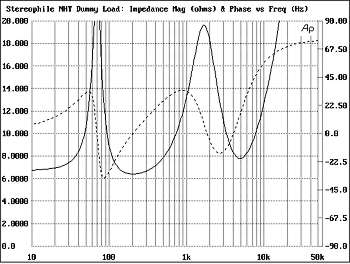

I found this model rather useful for a spice simulation of power Amp output transistor loading. JA's addition of the series RC net to better represent loading at HF was interesting because these Zobel nets are usually part of the amplifier not the speakers and are used together with the mandatory series inductance to stabilize the amp against capacitive loading.
The point I'm trying to make is that some crossover designs are of the 'constant resistance' (CR) types which try to flatten the peaks and troughs across the range this may be the reason why JA added the Zobel net not because it is intrinsically part of a speaker model but because CR crossovers can do that if used. The speakers JA alluded to presenting 'a less kind HF load' probably had CR crossovers of a sort..
I redesigned my Klipshorn mid/HF crossovers to a CR type as with the original XO's they could hardly be called 8 ohm speakers! The penalty is loss of efficiency (stated as 104dB/m for the KH) which hardly matters these days if using SS power amplifiers. CR XO's are more desirable with valve amps that need decent load lines for best linearity. Use of an autotransformer in the XO is useful if not mandatory to this end which is far from common practice. McIntosh use autotransformers in their SS amps because they know it's the best way to make life easier for the output devices faced with the current hungry reactive loads of many contemporary loudspeakers.
I would argue that amplifier testing at constant 4 or 8 ohms will not tell the full story in terms of how it will handle the wild dynamic load changes a real speaker will present without CR XO's. But neither would testing at sub 2 ohm loads which would be a rather unfair test because these load conditions occur over discrete bands and sustained excitation is unlikely with real music at least. Any decent amplifier should however be able to handle those sub 2 ohm levels for prescribed time intervals, derived from real music statistics, across the audio band at full rated power.
At any rate the issues arising with an amplifier driving reactive loads are far from novel or particular to audio power amps, the electrical power distribution companies have known about it for well over a century which they handle by encouraging POWER FACTOR CORRECTION. You can connect a 20uf capacitor across a power amplifier output at peak drive levels and deliver ZERO Watts (but lots of VAR's) yet the output devices will definitely get screaming hot. Of course PF correction in the same way is highly impractical in audio amps unless you are operating it at a single frequency say 50 or 60 Hz ... just to make the point. The nearest thing to PF correction would be a CR crossover.