| Columns Retired Columns & Blogs |
The DIY Chronicles, Part Four
Editor's Note: This is Part Four of a six-part series from reader Hervé Delétraz of Switzerland, who is chronicling the development of his DIY (do-it-yourself) audio amplifier. Part One is here, Part Two is here, and Part Three is here.
The prototype board was built in November 1999. I assembled all of the parts on a 6mm-thick aluminum plate and plugged it into the wall. Some buzzing noises for a while, then Waoum! Four devices in Heaven!
Well, the simulation was obviously working better than the real thing! I spent a few more nights—and transistors—and found some things that theory clearly showed me. The simulation didn't take all the parameters into account, which is normal after all. So I carried out the couple of mods needed and plugged in the beast again. No fire, no buzz, no harm. It was now November 11, 1999. From that date until now, not a single device has failed in dozens of hours of listening sessions.
 I still had to build the case. The simple aluminum plate was a little rustic, and no heatsinks were yet installed. In fact, the plate was so hot after 30 minutes that I had to run my machine with a Variac, at a reduced supply voltage. It was by using the amp at half the voltage that I discovered that the design worked perfectly with the same specs, with as low as 5V supplied! No more problem with wall-socket voltage variation, guys! From 40 to 140V (80–280V at home, in Geneva), the amp behaves like a charm, except of course the reduced output power available with lower supply voltages: physics is still physics, and my design doesn't come from Mars.
But as I started building the case, I couldn't stop thinking about the circuit itself, and how (and if) I could improve it before installing it in its case. After all—and I have to confess that I liked this fact—not a single exotic part was used. Only the cables were of audiophile grade: silver Kimber for input, copper Kimber for supplies and output. I used standard metal-film resistors, standard non-matched transistors, and standard caps—a real dream to maintain! Maybe top components for the future 2020 special edition? C'mon, babe, let the stuff be as is and we'll see!

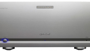
The amplifier with glass top removed.
The case took exactly nine months to make from scratch—just the right time to make a 42kg baby! I chose aluminum for the case and a glass cover. All screws are of nonmagnetic stainless steel. Because it's not so easy to cut, drill, and polish aluminum in the kitchen, I looked for some help. The cost question wasn't an issue for the prototype. I wanted it nice, rugged, solid as a rock, ready for demos.
A very good friend of mine, Henri-Michel, a skilled precision mechanic, offered to help me. (One of his hobbies is finishing watches for Patek Philippe.) All the aluminum plates were then adjusted, cut, drilled, polished, and finished by hand by my friend. The result is a unique one-off machine, a true prototype. Once the case was finished, I gave it to a small company for anodizing. This company has done work for Kudelski (Nagra) and Goldmund.
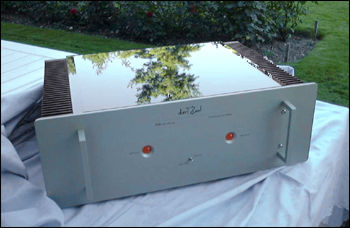
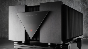
The finished amplifier case with glass top.
The only problem we encountered involved the only things we didn't make ourselves: the heatsinks. These huge, twice-normal size things caused some problems for the anodizing treatment. Some acid would stay in the punched fins, and affected the anodized color. The guy at the small company kindly told me that he began the process four times, but that the result would be less than perfect. Next time I'd better choose 100% extruded heatsinks if I wanted an evenly anodized color. But these look terrific!
Next week, Hervé Delétraz tests his amp and shares the results. Readers can contact him via e-mail at deletraz@bluewin.ch.
- Log in or register to post comments


| Loudspeakers Amplification Digital Sources | Analog Sources Accessories Featured | Music Columns Retired Columns | Show Reports | Features Latest News Community | Resources Subscriptions |
 © 2024 Stereophile
AVTech Media Americas Inc., USA
All rights reserved

