| Columns Retired Columns & Blogs |
Yamamoto A-08 power amplifier Measurements
Sidebar 3: Measurements
The Yamamoto A-08's two channels differed significantly in their voltage gains. Into 8 ohms at 1kHz, the right channel measured 19.85dB, the left 17.04dB. The circuit is mounted underneath the smart-looking wooden chassis. The review sample was missing the protective bottom plate; perhaps something had become misadjusted. The two channels also differed slightly when it came to output impedance. The right channel measured 3.2 ohms at 20Hz, dropping to 2.85 ohms at 1kHz and 2.16 ohms at 20kHz. The corresponding figures for the right channel were a little lower, at 3 ohms, 2.73 ohms, and 2.05 ohms, respectively, but these are still high in absolute terms.
The Yamamoto's noise floor was also different in the two channels. With the inputs shorted, the amplifier's A-weighted signal/noise ratios, which ignore both power-supply–related noise and RF noise, were similar at a modest 68dB ref. 2.83V into 8 ohms. With an unweighted, wideband measurement, while the right channel worsened only slightly, to 60dB, the left channel was quite a lot worse, at 47.5dB. On the positive side, the input impedance was a very high 200k ohms at bass and middle frequencies, dropping to a still high 129k ohms at 20kHz. The A-08 won't load down the preamplifier to any significant extent. The Yamamoto also preserved absolute polarity; ie, it was noninverting from input to output.
With its high source impedance, the A-08 featured a ±2dB modification of its frequency response driving our standard simulated loudspeaker load (fig.1, top trace at 2kHz). The ultrasonic rolloff was broken by a series of ultrasonic peaks, presumably due to output-transformer resonances, but was already down 3dB at 34kHz. The amplifier's reproduction of a 1kHz waveform was quite good (fig.2), with only a slight downward tilt to the flat top, this correlating with the rolloff below 20Hz seen in the frequency-response graph. The 10kHz squarewave (fig.3) suffered from increased risetimes and some damped ringing resulting from the ultrasonic resonances seen in fig.1.
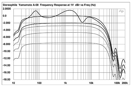
Fig.1 Yamamoto A-08, frequency response at 1V into (from top to bottom at 2kHz): simulated loudspeaker load, 8, 4, 2 ohms (1dB/vertical div., right channel dashed).
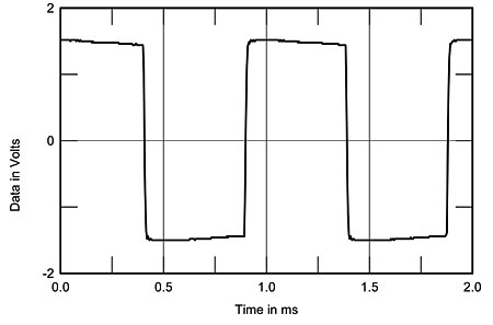
Fig.2 Yamamoto A-08, small-signal 1kHz squarewave into 8 ohms.
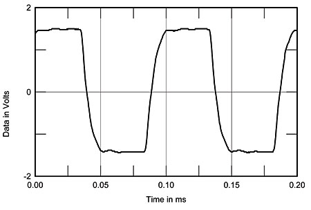
Fig.3 Yamamoto A-08, small-signal 10kHz squarewave into 8 ohms.
Channel separation (fig.4) was quite good in the upper midrange and mid-treble, but suffered from increasing crosstalk at low frequencies, presumably due to too high a power-supply impedance.
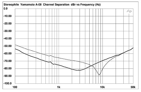
Fig.4 Yamamoto A-08, channel separation (10dB/vertical div., R–L dashed).
Assessing the A-08's maximum output power was somewhat of an exercise in frustration, due to the high levels of static distortion into any load. Despite the presence of those majestic-looking 45 output tubes, the A-08 can't deliver audibly distortion-free power at all. Fig.5 plots the percentage of THD+noise present in the amplifier's left-channel output into loads ranging from 16 to 2 ohms. Not much more than 300mW are available into 8 or 16 ohms at our usual definition of clipping of 1% THD. In fact, I had to relax the clipping definition to 3% THD for the A-08 to meet its specified output power of 2W into 8 ohms (3dBW). Perversely, it gave less power with higher distortion into 16 ohms than into 8 ohms.
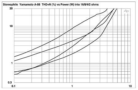
Fig.5 Yamamoto A-08, distortion (%) vs 1kHz continuous output power into (from bottom to top at 1W): 8, 16, 4, 2 ohms.
These measurements were performed on the left channel. As can be seen from the plot of THD+N against frequency (fig.6), the two channels differed significantly when it came to linearity. The right channel (solid trace) was actually quite a bit better than the left. And other than the rise in THD at low frequencies, due to the output transformer's core starting to saturate, the measured THD remains constant with frequency.
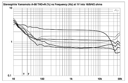
Fig.6 Yamamoto A-08, THD+N (%) vs frequency at 1V into (from bottom to top): 8, 16, 4, 2 ohms (left channel dashed).
The spectrum of the distortion is heavily second-harmonic, at least into 8 ohms from the left channel (fig.7), though at low frequencies, odd-order harmonics are also apparent (fig.8). Peculiarly, other than the second, the even-order harmonics decrease considerably in level at lower powers of low frequencies (fig.9). Finally, as I expected, the A-08 performed dismally on the high-frequency intermodulation test (fig.10), the 1kHz difference component reaching –45dB (0.6%) and the higher-order spuriae –38dB (1.2%).
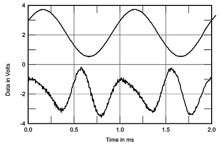
Fig.7 Yamamoto A-08, 1kHz waveform at 1V into 8 ohms (top), 0.6% THD+N; distortion and noise waveform with fundamental notched out (bottom, not to scale).
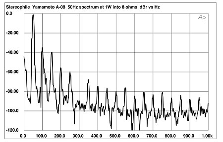
Fig.8 Yamamoto A-08, left channel, spectrum of 50Hz sinewave, DC–1kHz, at 1W into 8 ohms (linear frequency scale).
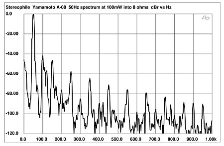
Fig.9 Yamamoto A-08, left channel, spectrum of 50Hz sinewave, DC–1kHz, at 100mW into 8 ohms (linear frequency scale).
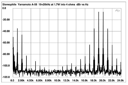
Fig.10 Yamamoto A-08, left channel, HF intermodulation spectrum, DC–24kHz, 19+20kHz at 1.3W peak into 8 ohms (linear frequency scale).
I don't think I need say anything more about the Yamamoto A-08's measured performance. It does look very handsome and it is beautifully made.—John Atkinson
|
| ||||||||||
- Log in or register to post comments


| Loudspeakers Amplification Digital Sources | Analog Sources Accessories Featured | Music Columns Retired Columns | Show Reports | Features Latest News Community | Resources Subscriptions |
 © 2024 Stereophile
AVTech Media Americas Inc., USA
All rights reserved

