| Columns Retired Columns & Blogs |
Waveform Research Mach 17 loudspeaker Measurements
Sidebar 3: Measurements
The Waveform Mach 17 is indeed very sensitive, with 2.83V of noise raising a sound-pressure level of 93.5dB/W/m at 1m. Figs.1–3 show the electrical impedance curves for the woofers, midrange, and tweeter respectively. Note that these are wideband curves, but in fact the partnering amplifiers will only see that portion of each drive-unit's impedance in its passband. The woofer curve, for example, shows some cabinet resonance-related spikes in the upper midrange, but these will not be excited in normal use. While the midrange is basically an 8 ohm device, the tweeter and woofer are 4 ohm-rated.
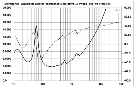
Fig.1 Waveform Mach 17 woofer, electrical impedance (solid) and phase (dashed) (2 ohms/vertical div.).
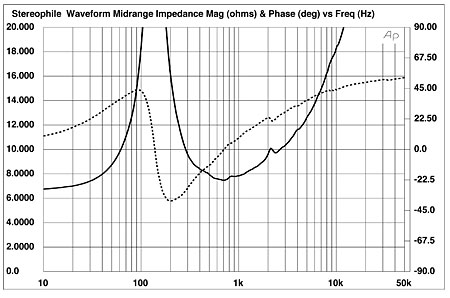
Fig.2 Waveform Mach 17 midrange unit, electrical impedance (solid) and phase (dashed) (2 ohms/vertical div.).
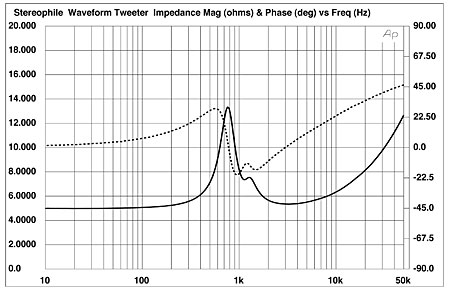
Fig.3 Waveform Mach 17 tweeter, electrical impedance (solid) and phase (dashed) (2 ohms/vertical div.).
The rather confusing plot in fig.4 shows the responses of the drive-units and ports without the crossover in-circuit. The woofers' reflex minimum-motion point occurs at a low 26Hz, with the port output broadly peaking between 20Hz and 70Hz. Without the crossover, the port output is low in level, however. The woofers' intrinsic response is quite extended, not rolling off until above 700Hz, but then with some vicious spikes in the low treble. The woofers are also a little more sensitive than the midrange unit, and a lot more so than the tweeter. The midrange unit's intrinsic response starts to roll out below 1kHz and above 4kHz, while the tweeter is basically flat above 2kHz.
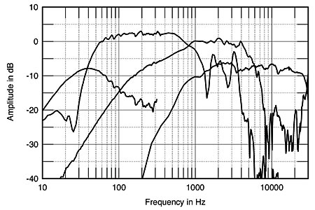
Fig.4 Waveform Mach 17, unequalized drive-unit responses on tweeter axis at 50", corrected for microphone response, with nearfield woofer and port responses plotted below 300Hz.
The crossover, of course, both equalizes and adjusts the sensitivities of the individual drive-units as well as implementing the high-, low-, and band-pass filter functions. Fig.5 shows the electrical responses of the three crossover outputs, with the controls in their maximum and minimum positions. You can see that the tweeter section both raises the gain to compensate for the driver's low sensitivity and offers a subtle tilt if necessary. The midrange section tightly defines the unit's passband, basically 400Hz to 1500Hz, while the woofer section offers a significant and adjustable degree of boost at the port tuning frequency.
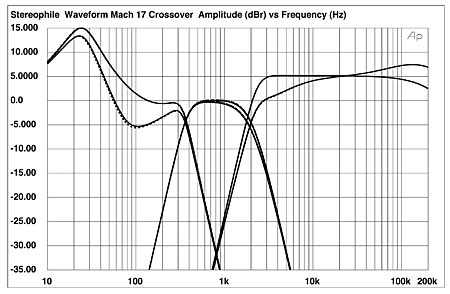
Fig.5 Waveform Mach 17 electronic crossover, electrical responses of tweeter, midrange, and woofer outputs with controls set to maximum and minimum positions (5dB/vertical div.).
The result of combining the drive-units' raw responses with the tonal shaping offered by the crossover—with the latter's controls set to their middle positions—is shown in fig.6. You can see that the port output now rises above the reference level. Note that the midrange bandpass responses seem a little too sensitive compared to those of the tweeter and woofer outputs. Note also the very steep acoustic filter slopes. Combining these individual responses, with the "egg" pointed straight ahead, results in the trace shown in fig.7. As suspected from fig.6, the upper midrange is a little prominent, but the response is otherwise very flat throughout the midrange and treble. The bass appears to peak up a little in this 2pi nearfield low-frequency measurement, but this will actually depend upon the room acoustics and the exact setting of the crossover bass control.
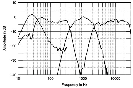
Fig.6 Waveform Mach 17, acoustic crossover on tweeter axis at 50", corrected for microphone response, with nearfield woofer and port responses plotted below 300Hz.
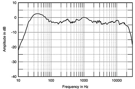
Fig.7 Waveform Mach 17, anechoic response on tweeter axis at 50", averaged across 30° horizontal window and corrected for microphone response, with complex sum of nearfield woofer and port responses plotted below 300Hz.
LG didn't remark on the upper mids sounding forward; in addition to the fact that this appears to be a simple matter of the midrange unit being a couple of dB too sensitive—something that can easily be compensated for by turning down the volume on just the midrange amplifier—fig.8 offers a possible explanation. The speaker's lateral dispersion is a little narrower in this region than it is above or below, which will make the room's reverberant field more evenly balanced. The tweeter output can be seen to fall off reasonably rapidly to the speaker's sides, which in an overdamped room will make the balance a little mellow.
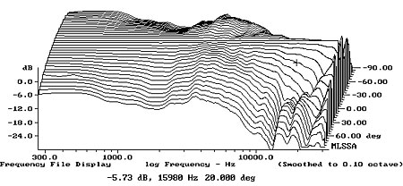
Fig.8 Waveform Mach 17, horizontal response family at 50", normalized to response on tweeter axis, from back to front: differences in response 90°–5° off-axis; reference response; differences in response 5°–90° off-axis.
In the vertical plane (fig.9), a notch develops at the upper crossover point if you sit significantly below the tweeter axis. I assume this is why LG ended up tilting the egg downward a little for his auditioning. But if you sit too high, the tweeter output falls off in the top octave, adding to the mellow balance noted above.
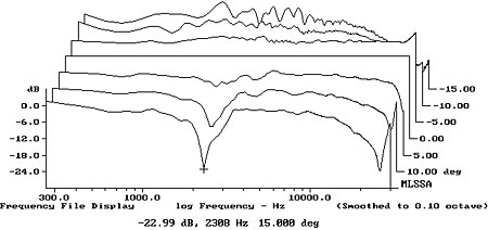
Fig.9 Waveform Mach 17, vertical response family at 50", normalized to response on tweeter axis, from back to front: differences in response 15°–5° above tweeter axis; reference response; differences in response 5°–15° below tweeter axis.
Fig.10 shows the Mach 17 head-unit's step response on the tweeter axis. This is hard to interpret, so figs.11 and 12 show the step responses of the tweeter and midrange units on this axis. You can see that the tweeter is connected with positive polarity, but the midrange step is initially negative-going, with a time delay of about 0.4ms. Fig.13 shows the step response of the equalized woofer module, which is also negative-going as well as following the midrange by about 2ms. (Remember that LG found he got the best integration between the woofer and midrange by reversing the former's polarity.) By no means can the Mach 17 be considered a time-coherent design.
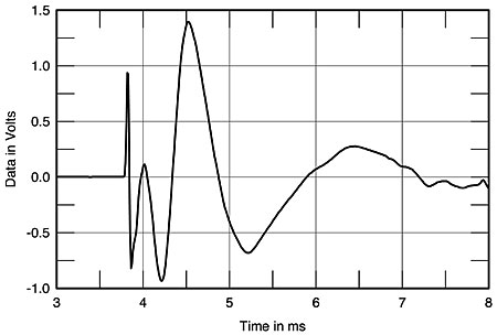
Fig.10 Waveform Mach 17 "egg" unit, step response on tweeter axis at 50" (5ms time window, 30kHz bandwidth).
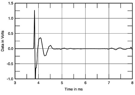
Fig.11 Waveform Mach 17 tweeter, step response on tweeter axis at 50" (5ms time window, 30kHz bandwidth).
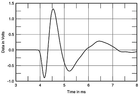
Fig.12 Waveform Mach 17 midrange unit, step response on tweeter axis at 50" (5ms time window, 30kHz bandwidth).
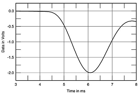
Fig.13 Waveform Mach 17 woofer, step response on tweeter axis at 50" (5ms time window, 30kHz bandwidth).
The cumulative spectral-decay or waterfall plot of the Waveform's head module is shown in fig.14. It is very clean throughout the treble, though a modicum of stored energy is apparent in the upper midrange.
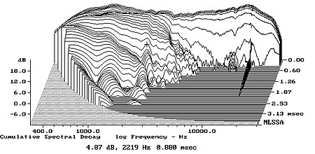
Fig.14 Waveform Mach 17, cumulative spectral-decay plot at 50" (0.15ms risetime).
Finally, using a simple plastic-tape accelerometer to investigate the resonant behavior of the cabinets revealed only out-of-band modes to be present in the woofer module. While the egg had a strong mode present at 420Hz, this is almost below the unit's passband, so its subjective effect should be negligible.
Overall, this is a pretty impressive set of measurements.—John Atkinson
|
| ||||||||||
- Log in or register to post comments


| Loudspeakers Amplification Digital Sources | Analog Sources Accessories Featured | Music Columns Retired Columns | Show Reports | Features Latest News Community | Resources Subscriptions |
 © 2024 Stereophile
AVTech Media Americas Inc., USA
All rights reserved

